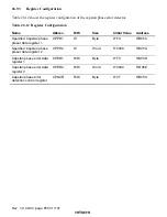
Rev. 1.0, 02/00, page 651 of 1141
26.9.4
Register Description
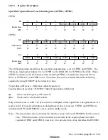
Specified Capstan Phase Preset Data Registers (CPPR1, CPPR2)
CPPR1
0
0
1
0
W
2
0
W
3
0
4
1
5
1
6
1
7
—
CPPR19
CPPR18
CPPR17
CPPR16
—
—
—
—
—
—
—
W
W
1
Bit :
Initial value :
R/W :
CPPR2
8
0
9
0
W
10
0
W
11
CPPR8
CPPR9
CPPR10
CPPR11
0
12
0
13
0
14
0
15
CPPR12
CPPR13
CPPR14
CPPR15
W
W
W
W
W
W
0
Bit :
Initial value :
R/W :
0
0
1
0
W
2
0
W
3
CPPR0
CPPR1
CPPR2
CPPR3
0
4
0
5
0
6
0
7
CPPR4
CPPR5
CPPR6
CPPR7
W
W
W
W
W
W
0
Bit :
Initial value :
R/W :
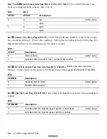
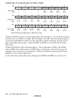
The 20-bit preset data that defines the specified capstan phase is set in CPPR1 and CPPR2. The
20 bits are weighted as follows: bit 3 of CPPR1 is the MSB. Bit 0 of CPPR2 is the LSB. When
CPPR2 is written to, the 20-bit preset data, including CPPR1, is loaded into the preset circuit.
Write to CPPR1 first, and CPPR2 next. The preset data can be calculated from the following
equation by using H'80000* as the reference value.
Target phase difference = Reference signal frequency/2
Capstan phase preset data = H'80000
−
(
φ
s/n
×
target phase difference)
φ
s:
Servo clock frequency in Hz (fosc/2)
φ
s/n:
Clock source of selected counter
Only a word access is valid. If a byte access is attempted, correct operation is not guaranteed. No
read is valid. If a read is attempted, an undetermined value is read out. CPPR1 and CPPR2 are
initialized to H'F0 and H'0000 by a reset, and in standby mode.
Note: The preset data value is calculated so that the counter will reach H'80000 when the error is
zero. When the counter value is latched as error data in the capstan phase error data
registers (CPER1 and CPER2), however, it is converted to a value referenced to H'00000.

