Rev. 1.0, 02/00, page 814 of 1141
28.3
Operation
28.3.1
Slice Line Specification
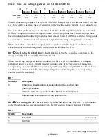
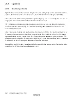
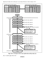
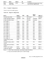
Up to four slice lines can be specified using the slice line setting registers 1 to 4. For information
on field discrimination, refer to section 27.2.6, Field Detection Window Register (FWIDR).
After completion of data slicing for all lines specified by registers, a slice completion interrupt is
output; the slice results and slice information should then be read.
Slice information includes clock run-in detection, start bit detection, and data end detection to
determine whether data sampling was performed normally; this information is stored in slice
detection registers 1 to 4.
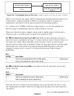
After completion of slicing for specified lines, the slice enable bit for the slice line setting register
is reset to 0. The next time the data slicer is operated, the slice enable bit of the slice line setting
register should be set to 1. At this time, the corresponding slice detection register is cleared. The
slice enable bit is sampled at the rising edge of the Vsync signal. Hence enabling of slice operation
is valid until the next Vsync signal after reset of the slice enable bit.
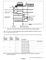
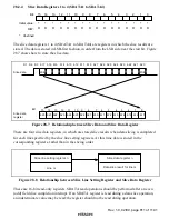
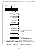
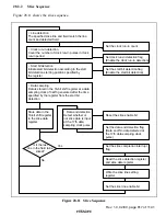
Figures 28.9 and 28.10 show examples of slice line specification and operation. For details, refer
to section 28.2.2, Slice Line Setting Registers 1 to 4.

