Rev. 1.0, 02/00, page 534 of 1141
25.2.2
Trap Address Register 2 to 0 (TAR2 to TAR0)
0
0
1
0
R/W
2
0
R/W
3
4
5
6
7
R/W
A18
A17
A16
0
0
R/W
0
R/W
R/W
A23
A22
A21
0
0
R/W
R/W
A20
A19
0
0
1
0
R/W
2
0
R/W
3
4
5
6
7
R/W
A10
A9
A8
0
0
R/W
0
R/W
R/W
A15
A14
A13
0
0
R/W
R/W
A12
A11
0
—
—
1
0
R/W
2
0
R/W
3
4
5
6
7
A2
A1
0
0
R/W
0
R/W
R/W
A7
A6
A5
0
0
R/W
R/W
A4
A3
0
Bit :
Initial value :
R/W :
Bit :
Initial value :
R/W :
Bit :
Initial value :
R/W :
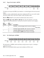
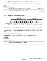
The TAR is composed of three 8-bit readable/writable registers (TARnA, B, and C)(n = 2 to 0)
The TAR sets the address to trap. The function of the TAR2 to TAR0 is the same.
The TAR is initialized to H'00 by a reset.
TARA bits 7 to 0: Addresses 23 to 16 (A23 to A16)
TARB bits 7 to 0: Addresses 15 to 8 (A15 to A8)
TARC bits 7 to 0: Addresses 7 to 1 (A7 to A1)
If the value installed in this register and internal address buses A23 to A1 match as a result of
comparison, an interruption occurs.
For the address to trap, set to the address where the first byte of an instruction exists. In the case
of other addresses, it may not be considered that the condition has been satisfied.
Bit 0 of this register is fixed at 0. The address to trap becomes an even address.
The range where comparison is made is H'000000 to H'FFFFFE.

