Rev. 1.0, 02/00, page 254 of 1141
12.1.3
Pin Configuration
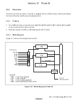
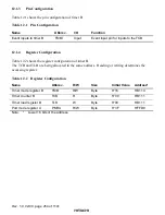
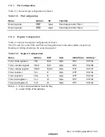
Table 12.1 shows the pin configuration of timer B.
Table 12.1
Pin Configuration
Name
Abbrev.
I/O
Function
Event inputs to timer B
TMBI
Input
Event input pin for inputs to the TCB
12.1.4
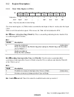
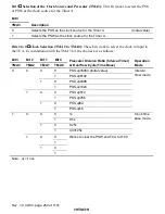
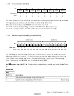
Register Configuration
Table 12.2 shows the register configuration of timer B.
The TCB and TLB are being allocated to the same address. Reading or writing determines the
accessing register.
Table 12.2
Register Configuration
Name
Abbrev.
R/W
Size
Initial Value
Address*
Timer mode register B
TMB
R/W
Byte
H'18
H'D110
Timer counter B
TCB
R
Byte
H'00
H'D111
Timer load register B
TLB
W
Byte
H'00
H'D111
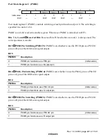
Port mode register A
PMRA
R/W
Byte
H'3F
H'FFD9
Note:
*
Lower 16 bits of the address.


