Rev. 1.0, 02/00, page 491 of 1141
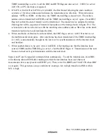
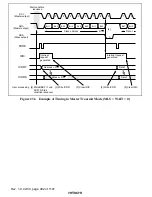
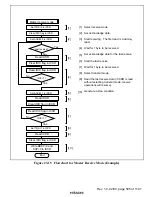
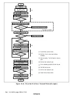
TDRE internal flag is set to 1 and the IRIC and IRTR flags are also set to 1. If IEIC is set to 1
in ICCR, a CPU interrupt is requested.
3. If bit FS is 0 in SAR or bit FSX is 0 in SARX, the first frame following the start condition
contains a 7-bit slave address and indicates the transmit/receive direction. Write data (slave
a R/
:
) to ICDR. At this time, the TDRE internal flag is cleared to 0. The written
address data is transferred to ICDRS, and the TDRE internal flag is set to 1 again. Clear IRIC
flag to 0 so that the end of transfer can be determined. The master device outputs the written
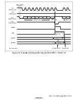
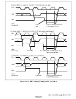
data together with a sequence of transmit clock pulses at the timing shown in figure 23.6. The
selected slave device (the device with the matching slave address) drives SDA low at the ninth
transmit clock pulse to acknowledge the data.
4. When one frame of data has been transmitted, the IRIC flag is set to 1 in ICCR at the rise of
the ninth transmit clock pulse. After one frame has been transferred, if the TDRE internal flag
is 1, SCL is automatically brought to the low level in synchronization with the internal clock
and held low.
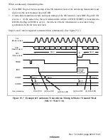
5. When another data is to be sent, write it in ICDR. After making sure that the data has been
sent to ICDRS and the TDRE flag is set to 1, clear the IRIC flag to 0. Transmission of the next
frame is turned on in synchronization with the internal clock.
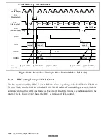
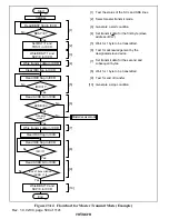
Steps 4 and 5 can be repeated to transmit data continuously. To end the transmission, clear IRIC,
write dummy data in ICDR after making sure that the last data has been sent (the next
transmission date is not present on ICDRT yet). Then, write 0 in BBSY and 0 in ICCR when IRIC
is set again. This generates a stop condition by causing a low-to-high transition of SDA while
SCL is high.

