Rev. 1.0, 02/00, page 262 of 1141
[Legend]
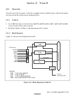
TCJ
Note: * At the Low level under the timer mode.
TLJ
: Timer counter J
: Timer load register J
TCK
TLK
: Timer counter K
: Timer load register K
TMO
REMOout
: TMJ-1 timer output
: TMJ-2 toggle output
(Remote controller
transmission data)
BUZZ
Reloading register
(Burst/space
width register
PS22, 21,20
EXN
: Buzzer output
TGL
: TMJ-2 toggle flag
PS22, 21,20
ST
: TMJ-2 input clock selection
: Starting the remote controlled operation
PS11,10
: TMJ-1 input clock selection
8/16
T/R
EXN
: 8-bit/16-bit operation changeover
: Timer output/Remote controller output changeover
: Expansion function switching
Internal data bus
Edge
detection
Toggle
T/R
Down-counter
(8/16-bit)
BUSS
Output
Control
Monitor
Output
Control
Toggle
Reloading
register
8/16
ST
PS11,10
Down-
counter (8-bit)
UnderÐ
flow
Under-
flow
TCJ
TMJ-1
TMJ-2
TCK
PB/REC-CTL
DVCTL
TCA7
φ
/4096
φ
/8192
TGL
REMOout
TMO
TMO
BUZZ
Clock sources
IRQ2
φ
/64
φ
/128
φ
/1024
φ
/2048
φ
/16384
Clock sources
IRQ1
φ
/4
φ
/256
φ
/512
*
Synchronization
TLJ
Reloading
Reloading
TLK
TMJ-1
Interrupting circuit
Interrupt request
by the TMJ1I
Interrupt request
by the TMJ2I
TMJ-2
Interrupting circuit
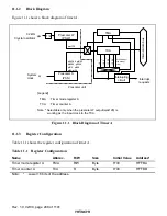
Figure 13.1 Block Diagram of timer J

