Rev. 1.0, 02/00, page 396 of 1141
21.4.4
8-bit PWM
This 8-bit PWM controls the duty control PWM signal in the conversion cycle 256 states. It
counts the cycle and the duty cycle at 2
7
to 2
0
of the FRC. It can be used for controlling reel
motors and loading motors. For details, see section 18, 8-Bit PWM.
21.4.5
8-bit Input Capture Using
,&
,&
,&
,&
Pin
This function catches the 8-bit data of 2
15
to 2
8
of the FRC according to the edge of the
,&
pin. It
can be used for remote control receiving.
For the edge of the
,&
pin, the rising and falling edges can be selected.
The
,&
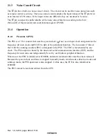
pin has a built-in noise cancel circuit. See section 21.3, Noise Cancel Circuit.
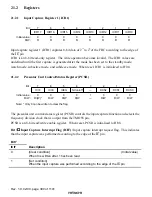
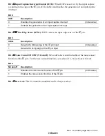
An interrupt request is generated due to the input capture using the
,&
pin.
Note:
Rewriting the ICEG bit, NCon/off bit, or PMR16 bit is incorrectly recognized as edge
detection according to the combinations between the state and detection edge of the
,&
pin
and the ICIF bit may be set after up to 384
φ
seconds.
21.4.6
Frequency Division Clock Output
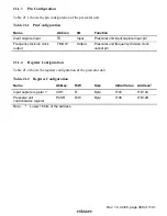
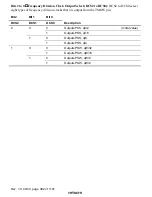
The frequency division clock can be output from the TMOW pin. For the frequency division
clock, eight types of clocks can be selected according to the DCS2 to DCS0 bits in PCSR.
The clock in which the system clock was frequency-divided is output in active mode and sleep
mode and the clock in which the subclock was frequency-divided is output in active mode*, sleep
mode*, and subactive mode.
Note: *
When timer A is in module stop mode, no clock is output.


