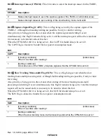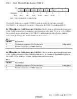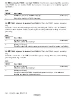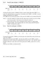
Rev. 1.0, 02/00, page 290 of 1141
Notes:
Internal bus
Internal bus
Clock sources
DVCTL
CFG
↑
Clock
selection (2 bits)
Reloading register
(8 bits)
Down-counter
(8 bits)
Capture register
(8 bits)
TMRI2
Interrupt request
TMRI1
Interrupt
request
TMRI3
Interrupt
request
TMRU-1
TMRCP1
*2
Under–
flow
TMRU-3
Underflow
*1
TMRL3
PS31,30
External signals
IRQ3
φ
/1024
φ
/2048
φ
/4096
Clock source
φ
/64
φ
/128
φ
/256
Clock sources
φ
/4
φ
/256
φ
/512
Down-counter
(8 bits)
Latch
clock
selection
Clock
selection (2 bits)
Resetting Available/
Not
available
CP/
SLM
SLW
CAPF
Capture register
(8 bits)
Down-counter
(8 bits)
Reloading register
(8 bits)
Acceleration/
braking
Reloading Available/
not
available
Reloading
clock
selection
Reloading register
(8 bits)
RLD/
CAP
Clock
selection
(2 bits)
CPS
LAT
PS21,20
CLR2
Res
Res
TMRCP2
Under–
flow
TMRU-2
CFG mask F/F
R
S
Q
R
S
Q
Acceleration
braking
AC/BR
TMRL2
RLD
RLCK
TMRL1
PS11,10
Interrupting circuit
1.
When the DVCTL is being used as the clock source, reloading will be made when the counter underflows and when
the dividing clock is being used as the clock source, reloading will be made by the DVCTL.
2.
When the LAT bit = 0, the capture signal against the TMRU-1 will not be output.
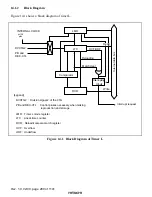
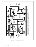
Figure 15.1 Block Diagram of Timer R

