Rev. 1.0, 02/00, page 174 of 1141
9.2
Register Descriptions
9.2.1
Standby Control Register (SBYCR)
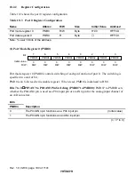
7
SSBY
0
R/W
6
STS2
0
R/W
5
STS1
0
R/W
4
STS0
0
R/W
3
—
0
—
0
SCK0
0
R/W
2
—
0
—
1
SCK1
0
R/W
Bit
Initial value
R/W
:
:
:
SBYCR is an 8-bit readable/writable register that performs power-down mode control.
Only bits 0 and 1 are described here. For a description of the other bits, see section 4.2.1, Standby
Control Register (SBYCR). SBYCR is initialized to H'00 by a reset.
Bits 1 and 0
System Clock Select 1 and 0 (SCK1, SCK0): These bits select the bus master
clock for high-speed mode and medium-speed mode.
Bit 1
Bit 0
SCK1
SCK0
Description
0
Bus master is in high-speed mode
(Initial value)
0
1
Medium-speed clock is
φ
/16
0
Medium-speed clock is
φ
/32
1
1
Medium-speed clock is
φ
/64


