Rev. 1.0, 02/00, page 811 of 1141
28.2.4
Slice Data Registers 1 to 4 (SDATA1 to SDATA4)
15
*
R
14
*
R
13
*
R
12
*
R
11
*
R
10
*
R
9
*
R
8
*
R
7
*
R
6
*
R
5
*
R
4
*
R
3
*
R
2
*
R
1
*
R
0
*
R
Bit:
Initial value:
R/W:
*:
Unefined
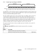
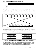
The slice data registers 1 to 4 (SDATA1 to SDATA4) are registers in which the slice results are
stored. The data is stored in LSB-first fashion, in order from the LSB side near the start bit. Figure
28.7 shows how to store the slice data.
15
b20
14
b21
13
b22
12
b23
11
b24
10
b25
9
b26
8
b27
7
b10
6
b11
5
b12
4
b13
3
b14
2
b15
1
b16
0
b17
b17
S3
S2
S1
b16 b15
b14
b13
b12 b11 b10 b27 b26
b25 b24 b23 b22 b21 b20
LSB
MSB
Bit
Slice data
register
Slice data
Figure 28.7 Relationship between Slice Data and Slice Data Register
There are four slice data registers, in which are stored slice results when data slicing is completed
for each line specified by the slice line setting registers. At this time data is stored in the
corresponding registers, rather than in the slicing order.
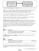
Slice line setting register n
Line m
Slice data register n
Data slice result for line m
Figure 28.8 Relationship between Slice Line Setting Register and Slice Data Register
These are 16-bit read-only registers. SDATA read operations should be performed after an even
(odd) field slice completion interrupt. If an SDATA register is read during a data slice operation,
an indeterminate value may be read; the register should not be read during operation.

