Rev. 1.0, 02/00, page 10 of 1141
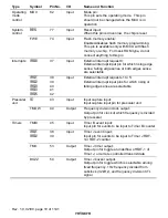
Type
Symbol
Pin No.
I/O
Name and Function
Operating
mode
control
MD0
82
Input
Mode pin:
This pin sets the operating mode. This pin
should not be changed while the MCU is in
operation
5(6
77
Input
Reset input:
When this pin is driven low, the chip is reset
System
control
FWE
74
Input
Flash memory enable:
Enables/disables flash memory programming.
This pin is available only with MCU with flash
memory on-chip. For mask ROM type, do not
connect anything to this pin
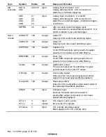
,54
3
37
Input
External interrupt request 0:
External interrupt input pin for which rising edge
sense, falling edge sense or both edges sense
are selectable
Interrupts
,54
4
,54
5
,54
6
,54
7
,54
8
38
39
40
41
42
Input
External interrupt requests 1 to 5:
External interrupt input pins for which rising or
falling edge sense are selectable
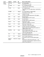
,&
43
Input
Input capture input:
Input capture input pin for prescaler unit
Prescaler
unit
TMOW
44
Output
Frequency division clock output:
Output pin for clock of which frequency is divided
by prescaler
TMBI
45
Input
Timer B event input:
Input pin for events to be input to Timer B counter
,54
4
,54
5
38
39
Input
Timer J event input:
Input pin for events to be input to Timer J RDT-
1or RDT-2 counter
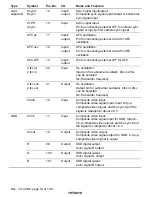
TMO
53
Output
Timer J timer output:
Output pin for toggle at underflow of RDT-1 of
Timer J, or remote controlled transmit data
Timers
BUZZ
54
Output
Timer J buzzer output:
Output pin for toggle which is selectable among
fixed frequency, 1Hz frequency divided from
subclock (32 kHz), and frequency division CTL
signal


