Rev. 1.0, 02/00, page 709 of 1141
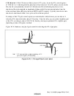
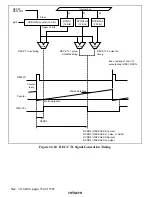
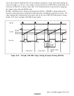
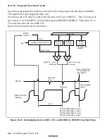
Figure 26.56 shows the duty discrimination circuit. A 44% duty cycle is discriminated by
counting with the 16-bit up/down counter, using a
φ
s/4 clock for the up-count and a
φ
s/5 clock for
the down-count. An up-count is performed when the PB-CTL signal is high, and a down-count
when low. Long or short pulse is discriminated by comparing with RCDR2 to RCDR5.
Counter
PB-CTL
1 pulse
PB-CTL
↑
PB-CTL
φ
s/4
φ
s/5
Counter
PB-CTL
0 pulse
φ
s/4
φ
s/5
Counter
FWD
PB-CTL
Short pulse
(0 pulse)
φ
s/4
φ
s/5
RCDR3
RCDR2
0 pulse L/S threshold value
1 pulse L/S threshold value
Counter
REV
PB-CTL
Long pulse
(1 pulse)
φ
s/5
φ
s/4
RCDR4
RCDR5
0 pulse L/S threshold value
1 pulse L/S threshold value
UP/DOWN
Comparison of upper
12-bit
UP/DOWN counter (16 bits)
* RCDR2or4 (12bit)
* FWD : Discriminated by RCDR2 and RCDR3
REV : Discriminated by RCDR4 and RCDR5
* RCDR3or5 (12bit)
0/1
discrimination
UDF
Clear
R
S
Q
φ
s/4
φ
s/5
L/S
discrimination
Figure 26.56 Duty Discriminator

