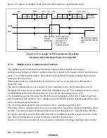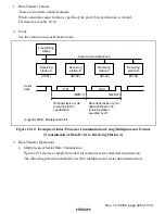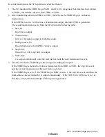
Rev. 1.0, 02/00, page 423 of 1141
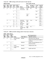
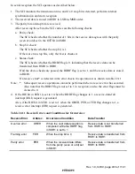
Table 22.8
SMR1 Settings and Serial Transfer Format Selection
SMR1 Settings
SCI Transfer Format
Bit 7
Bit 6
Bit 2
Bit 5
Bit 3
C/
$
$$
$
CHR
MP
PE
STOP
Mode
Data
Length
Multiproc-
essor Bit
Parity
Bit
Stop Bit
Length
0
1 bit
0
1
No
2 bits
0
1 bit
0
1
1
8-bit
data
Yes
2 bits
0
1 bit
0
1
No
2 bits
0
1 bit
1
0
1
1
Asynchro-
nous mode
7-bit
data
No
Yes
2 bits
0
1 bit
0
1
8-bit
data
2 bits
0
1 bit
0
1
1
1
Asynchro-
nous mode
(multi-
processor
format)
7-bit
data
Yes
2 bits
1
Clock
synchronous
mode
8-bit
data
No
No
Table 22.9
SMR1 and SCR1 Settings and SCI Clock Source Selection
SMR1 SCR1 Setting
Bit 7
Bit 1
Bit 0
SCI Transfer Clock
C/
$
$$
$
CKE1
CKE0
Mode
Clock Source
SCK Pin Function
0
SCI does not use SCK pin
0
1
Internal
Outputs clock with same frequency
as bit rate
0
0
1
1
Asynchronous
mode
External
Inputs clock with frequency of 16
times the bit rate
0
0
1
Internal
Outputs serial clock
0
1
1
1
Clock
synchronous
mode
External
Inputs serial clock


