Rev. 1.0, 02/00, page 373 of 1141
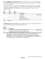
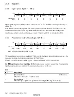
Bits 5 and 4
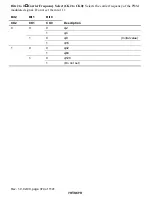
PWM Pin Output (HiZ, H/L): When bit DC is set to 1, the 12-bit PWM output
pins (CAPPWM, DRMPWM) output a value determined by the HiZ and H/L bits. The output is
not affected by bit POL.
In power-down modes, the 12-bit PWM circuit and pin statuses are retained. Before making a
transition to a power-down mode, first set bits 6 (DC), 5 (HiZ), and 4 (H/L) of the 12-bit PWM
control registers (CPWCR and DPWCR) to select a fixed output level. Choose one of the
following settings:
Bit 6
Bit 5
Bit 4
DC
HiZ
H/L
Output state
0
Low output
(Initial value)
0
1
High output
1
1
*
High-impedance
0
*
*
Modulation signal output
Note:
*
Don't care
Bit 3
Output Data Select (SF/DF): Selects whether the data to be converted to PWM output is
taken from the data register or from the digital filter circuit.
Bit 3
SF/DF
Description
0
Modulation by error data from the digital filter circuit
(Initial value)
1
Modulation by error data written in the data register
Note:
When PWMs output data from the digital filter circuit, the data consisting of the speed and
phase filtering results are modulated by PWMs and output from the CAPPWM and
DRMPWM pins. However, it is possible to output only drum phase filter results from
CAPPWM pin and only capstan phase filter result from DRMPWM pin, by DFUCR settings
of the digital filter circuit. See section 26.11, Digital Filters.


