Rev. 1.0, 02/00, page 264 of 1141
13.2
Register Descriptions
13.2.1
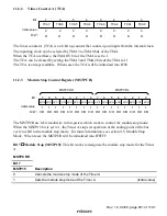
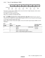
Timer Mode Register J (TMJ)
0
0
1
0
R
2
0
R/W
3
0
4
0
R/W
5
0
6
0
7
R/W
R/W
R/W
ST
R/W
PS10
0
R/W
PS11
8/16
PS21
PS20
TGL
T/R
Bit :
Initial value :
R/W :
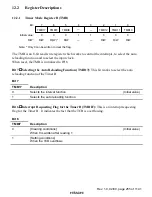
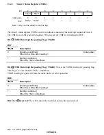
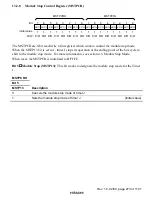
The timer mode register J (TMJ) works to select the inputting clock for the TMJ-1 and TMJ-2 and
to set the operation mode.
The TMJ is an 8-bit register and bit 1 is for read only. All the remaining bits are applicable to
read/write.
When reset, the TMJ is initialized to H'00.
Under all other modes than the remote controlling mode, writing into the TMJ works to initialize
the counters (TCJ and TCK) to H'FF.
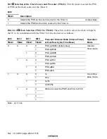
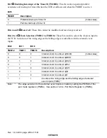
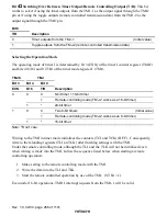
Bits 7 and 6
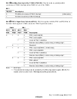
Selecting the Inputting Clock to the TMJ-1 (PS11 and PS10): These bits work
to select the clock to input to the TMJ-1. When the external clock is selected, the counted edge
(rising or falling) can also be selected.
Bit 7
Bit 6
PS11
PS10
Description
0
Counting by the PSS,
φ
/512
(Initial value)
0
1
Counting by the PSS,
φ
/256
0
Counting by the PSS,
φ
/4
1
1
Counting at the rising edge or the falling edge of the external clock
inputs (
,54
4
) *
Note:
*
The edge selection for the external clock inputs is made by setting the IRQ edge select
register (IEGR). See section 6.2.4, IRQ Edge Select Register (IEGR) for more
information.
When using an external clock under the remote controlling mode, set the opposite edge
with the IRQ1 and the IRQ2 when using an external clock under the remote controlling
mode. (When IRQ1 falling, select IRQ2 rising and when IRQ1 rising, select IRQ2
falling)

