


Rev. 1.0, 02/00, page 684 of 1141
26.13
CTL Circuit
26.13.1
Overview
The CTL circuit includes a Schmitt amplifier that amplifies and reshapes the CTL input, then
outputs it as the PB-CTL signal to the servo, linear time counter, and other circuits.
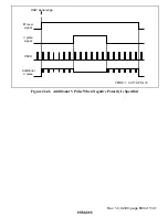
The PB-CTL signal is also sent to a duty discriminator in the CTL circuit that detects and records
VISS, ASM, and VASS marks. A REC-CTL amplifier is included in the record circuits.
Detection and recording whether the CTL pulse pattern is long or short can also be enabled to
correspond to the wide-aspect.
The following operating modes can be selected by settings in the CTL mode register:
•
Duty discrimination
VISS detect, ASM detect, VASS detect, L/S bit pattern detect
•
CTL record
VISS record, ASM record, VASS record, L/S bit pattern record
•
Rewrite
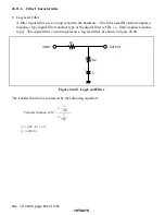
Trapezoid waveform generator