Rev. 1.0, 02/00, page 806 of 1141
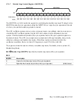
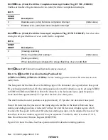
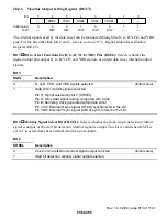
Bits 4 to 0
Data Sampling Delay Time Setting Bits (DLYE4 to DLYE0) (DLYO4 to
DLYO0): Set the even (odd) field data sampling clock delay time.
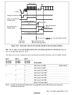
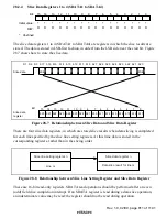
Figure 28.3 explains the data sampling clock.
The data sampling clock is a clock with period 32
×
fh, used for slicing 16-bit closed caption data.
The data sampling clock is generated after the rising edge of the start bit is detected and the time
set by the DLY bit is passed. The delay time setting can be adjusted in units of 576
×
fh, so that
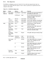
sampling is possible at a phase optimal for the slice data. The data sampling delay time (TD)
should be set based on the calculation indicated below. Eighteen pulses of data sampling clock are
output in total for start bit detection, slice data, and end data detection. In order to make the
sampling phase even more optimal, the slice data (analog comparator output) and sampling clock
can be output from the port. For details of monitor output, refer to section 28.2.6, Monitor Output
Setting Register (DOUT).
TD = 111.1 ns (1/576
×
fh)
×
[setting in bits DLY4 to DLY0 + 2]
fh: Horizontal sync signal frequency
Start
bit
Slice data
1st character
S1 S2
32
×
fh
S3
b7 b6 b5 b4 b3 b2 b1 b0 b7 b6 b5 b4 b3 b2 b1 b0
LSB
2nd character
Detected start
bit
Data sampling
clock
32
×
fh
TD: Data sampling delay time specified by DLYE4 to DLYE0 (DLYO4 to DLYO0)
TD = ns
×
[setting in bits DLY4 to DLY0 + 2]
MSB
1
576
×
fh
Figure 28.3 Data Sampling Clock Description

