Rev. 1.0, 02/00, page 219 of 1141
10.7.2
Register Configuration
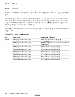
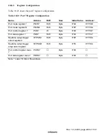
Table 10.18 shows the port 6 register configuration.
Table 10.18 Port 6 Register Configuration
Name
Abbrev.
R/W
Size
Initial Value
Address
*
Port mode register 6
PMR6
R/W
Byte
H'00
H'FFDD
Port mode register A
PMRA
R/W
Byte
H'3F
H'FFD9
Port control register 6
PCR6
W
Byte
H'00
H'FFD6
Port data register 6
PDR6
R/W
Byte
H'00
H'FFC6
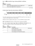
Realtime output trigger
select register 1
RTPSR1
R/W
Byte
H'00
H'FFE5
Realtime output trigger
edge select register
RTPEGR
*
2
R/W
Byte
H'FC
H'FFE4
Port control register slave
6
PCRS6
Byte
H'00
Port data register slave 6
PDRS6
Byte
H'00
Notes: 1. Lower 16 bits of the address.
2. RTPEGR is also used by port 7.
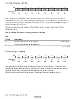
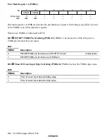
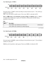
Port Mode Register 6 (PMR6)
0
0
1
0
R/W
2
0
R/W
3
0
4
0
R/W
0
R/W
5
6
0
7
PMR64
PMR63
PMR62
PMR61
PMR60
0
R/W
PMR67
R/W
R/W
R/W
PMR66
PMR65
Bit :
Initial value :
R/W :
Port mode register 6 (PMR6) controls switching of each pin function of port 6. The switching is
specified in units of bits.
PMR6 is an 8-bit read/write enable register. When reset, PMR6 is initialized to H'00.
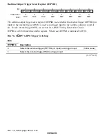
Bits 7 to 0
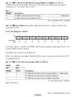
P67/RP7 to P60/RP0 Pin Switching (PMR67 to PMR60): PMR67 to PMR60 set
whether the P6n/RPn pin is used as a P6n I/O pin or an RPn pin for the realtime output port.
Bit n
PMR6n
Description
0
The P6n/RPn pin functions as a P6n I/O pin
(Initial value)
1
The P6n/RPn pin functions as an RPn output pin
(n = 7 to 0)


