Rev. 1.0, 02/00, page 697 of 1141
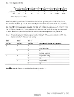
Duty I/O Register (DI/O)
0
1
1
0
R/(W)*
2
0
W
3
0
4
—
—
5
1
6
7
R/W
W
W
VCTR0
1
W
VCTR1
1
W
VCTR2
BPON
BPS
BPF
DI/O
1
Note: * Only 0 can be written
Bit :
Initial value :
R/W :
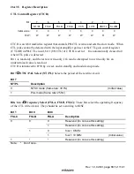
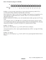
DI/O is an 8-bit register that confirms and determines the operating status of the CTL circuit.
It is initialized to H'F1 by a reset, and in standby mode, module stop mode, and CTL stop mode.
Bits 7 to 5
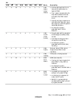
VISS Interrupt Setting Bit (VCTR2 to VCTR0): Combination of VCTR2, VCTR1
and VCTR0 sets number of 1 pulse detection in VISS detection mode. Detecting the set number
of pulse detection is considered as VISS detection, and an interrupt request is generated.
Note:
When changing the detection pulse number during VISS detection, initialize VISS first,
then resume the VISS detection setting.
Bit 7
Bit 6
Bit 5
VCTR2
VCTR1
VCTR0
Number of 1-Pulse for Detection
0
2
0
1
4 (SYNC mark)
0
6
0
1
1
8 (mark A, short)
0
12 (mark A, long)
0
1
16
0
24 (mark B)
1
1
1
32
Bit 4
Reserved: Cannot be modified and is always read as 1.

