Rev. 1.0, 02/00, page 720 of 1141
Bit 1
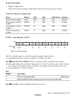
HSW Flag (HSW): Shows the level of the HSW signal selected by the VFF/NFF bit of the
HSW mode register 2 (HSM2).
Bit 1
HSW
Description
0
HSW is at low level
(Initial value)
1
HSW is at high level
Bit 0
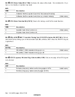
CTL Flag (CTL): Shows the CTL level.
Bit 0
CTL
Description
0
REC or PB-CTL is at low level
(Initial value)
1
REC or PB-CTL is at high level
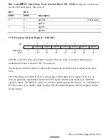
CTL Frequency Division Register (CTLR)
0
0
1
0
W
2
0
W
3
0
4
0
W
0
W
5
6
0
7
CTL4
CTL3
CTL2
CTL1
CTL0
0
W
CTL7
W
W
W
CTL6
CTL5
Bit :
Initial value :
R/W :
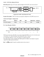
CTLR is an 8-bit write-only register to set the frequency dividing value (N-1 if divided by N) for
PB-CTL. If a read is attempted, an undetermined value is read out.
PB-CTL is divided by N at its rising edge. If the register value is 0, no division operation is
performed, and the DVCTL signal with the same cycle with PB-CTL is output. It is initialized by
a reset or in stand-by mode.


