Rev. 1.0, 02/00, page 761 of 1141
27.2
Register Description
27.2.1
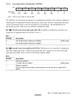
Sync Separation Input Mode Register (SEPIMR)
0
0
0
0
0
0
0
0
7
R/W
FRQSEL
0
R/W
CCMPV1
6
R/W
CCMPV0
5
R/W
COMPSL
4
R/W
SYNCT
3
R/W
VSEL
2
R/W
DLPFON
1
—
—
Bit :
Initial value :
R/W :
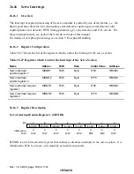
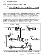
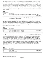
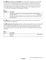
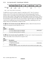
The SEPIMR is an 8-bit read/write register for selecting the source signals for sync separation. In
addition to the internal switches controlled by this register setting, the external circuits are used to
select the sources of the Hsync and Vsync signals to be supplied to the digital H separation
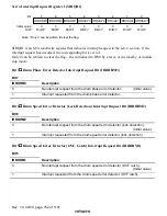
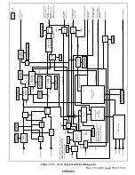
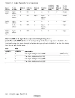
counter and the digital V separation counter, respectively. Figure 27.2 and table 27.3 show the
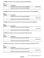
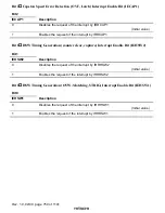
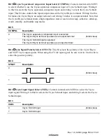
source signal selection. The SEPIMR also specifies the slicing voltage of the Csync separation
comparator, switches the polarity of the signals input from the Csync/Hsync and VLPF/Vsync
terminals, turns on or off the digital LPF, and switches the reference clock frequency for the AFC.
For details on the source signals for sync separation, refer to section 27.3.1, Selecting Source
Signals for Sync Separation. When reset, the SEPIMR is initialized to H'00.
CVin2
Csync
a
1
1
0
0
b
a
b
Hsync
Vsync
VLPF
VLPF/Vsync
Csync/Hsync
Hsync
Vsync
DLPFON
External
SW3
Internal
SW5
Internal
SW6
External
SW2
External
SW1
Reference
voltage switch
Register
control
I/O
switch
I/O
switch
Polarity
switch
Sync tip
clamp
Digital V
separation
counter
Csync polarity
Schmitt circuit
Vsync polarity
Schmitt circuit
External circuit
Inside LSI
Csync
separation
comparator
External
SW4
CVin2
–
+
CCMPSL
CCMPV0, 1
SYNCT
VSEL
SEPV
SEPH
Digital H
separation
counter
Polarity
switch
Figure 27.2 Diagram of the Circuit for Selecting the Source Signals for Sync Separation


