Rev. 1.0, 02/00, page 690 of 1141
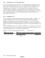
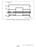
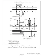
CTL input
PB-CTL
FWD
REV
Figure 26.48 Internal PB-CTL Signal in Forward and Reverse
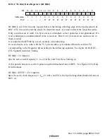
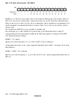
Bits 4 to 0
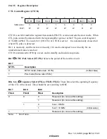
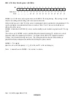
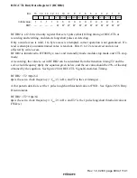
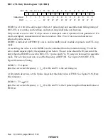
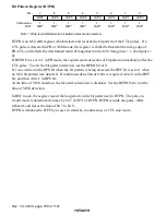
CTL Mode Select (MD4 to MD0): These bits select the detect, record, and rewrite
modes for VISS, VASS, and ASM marks. If 1 is written in bits MD3 and MD2, they will be
cleared to 0 one cycle (
φ
) later.
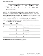
The 5 bits from MD4 to MD0 are used in combination with bits 7 and 6 (ASM and REC/
3%
).
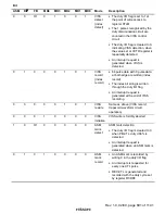
Table 26.20 describes the modes.
Table 26.20 CTL Mode Functions
Bit
ASM
R/
3
33
3
F/R
MD4
MD3
MD2
MD1
MD0
Mode
Description
0
0
0/1
0
0
0
0
0
VASS
detect
(duty
detect)
PB-CTL duty discrimination
(Initial value)
•
Duty I/O flag is set to 1 if duty
≥
44% is detected
•
Duty I/O flag is cleared to 0 if
duty < 44% is detected
•
Interrupt request is generated
when one CTL pulse has been
detected
0
1
0
0
0
0
0
0
VASS
record
•
If 0 is written in the duty I/O flag,
REC-CTL is generated and
recorded with the duty cycle set
by register RCDR2 or RCDR3
•
If 1 is written in the duty I/O flag,
REC-CTL is generated and
recorded with the duty cycle set
by register RCDR4 or RCDR5
0
0
0
1
0
0
1
0
VASS
rewrite
Same as above (VASS record);
trapezoid waveform circuit
operation

