Rev. 1.0, 02/00, page 201 of 1141
10.4.3
Pin Functions
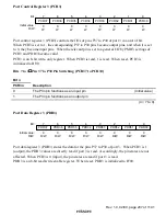
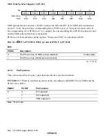
This section describes the port 2 pin functions and their selection methods.
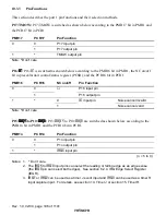
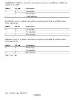
P27/SYNCI: P27/SYNCI is switched as shown below according to the PCR27 bit in PCR2.
PCR
Pin Function
0
P27 input pin
1
P27 output pin
Note:
Because the SYNCI always functions, the alternative pin need always be set to the high or
low level regardless of active mode or low power consumption mode.
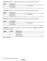
P26/SCL0: P26/SCL0 is switched as shown below according to the PCR26 bit in PCR2 and the
II0CE bit in the I
2
C Bus control register (ICCR0).
II0CE
PCR26
Pin Function
0
P26 input pin
0
1
P26 output pin
1
*
SCL0 I/O pin
Note:
*
Don’t care
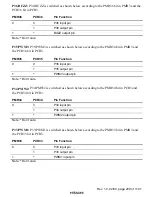
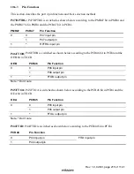
P25/SDA0: P25/SDA0 is switched as shown below according to the PCR25 bit in PCR2 and the
II0CE bit in the I
2
C Bus control register (ICCR0).
II0CE
PCR25
Pin Function
0
P25 input pin
0
1
P25 output pin
1
*
SDA0 I/O pin
Note:
*
Don’t care
P24/SCL1: P24/SCL1 is switched as shown below according to the PCR24 bit in PCR2 and the
II1CE bit in the I
2
C Bus control register (ICCR1).
II1CE
PCR24
Pin Function
0
P24 input pin
0
1
P24 output pin
1
*
SCL1 I/O pin
Note:
*
Don’t care

