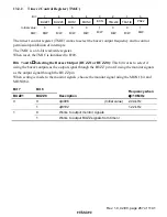
Rev. 1.0, 02/00, page 266 of 1141
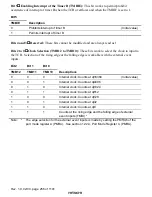
Bit 0
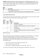
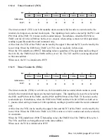
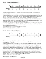
Switching Over Between Timer Output/Remote Controlling Output (T/R): This bit
works to select if using the timer outputs from the TMJ-1 as the output signal through the TMO
pin or if using the toggle outputs (remote controlled transmission data) from the TMJ-2 as the
output signal through the TMO pin.
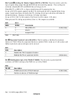
Bit 0
T/R
Description
0
Timer outputs from the TMJ-1
(Initial value)
1
Toggle outputs from the TMJ-2 (remote controlled transmission data)
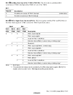
Selecting the Operation Mode
The operating mode of timer J is determined by bit 3 (EXN) of the timer J control register (TMJC)
and bits 4 (8/16) and 0 (T/R) of the timer mode register J (TMJ).
TMJC
TMJ
Bit 3
Bit 4
Bit 0
EXN
8/16
T/R
Description
0
0
0
8-bit timer + 16-bit timer
1
Remote-controlling mode (TMJ-2 works as a 16-bit timer)
1
*
24-bit timer
1
0
0
Two 8-bit timers
(Initial value)
1
Remote-controlling mode (TMJ-2 works as an 8-bit timer)
1
*
16-bit timer
Note:
*
Don’t care
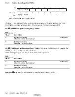
Writing to the TMJ in timer mode initializes the counters (TCJ and TCK) (H'FF). Consequently,
write to the reloading registers (TLJ an TLK) after finishing settings with the TMJ.
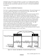
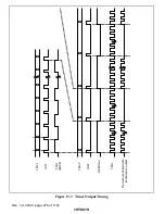
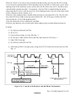
Under the remote controlling mode, although the TLJ and the TLK will not be initialized even
when writing is made into the TMJ, follow the sequence listed below when starting a remote
controlling operation:
1. Make setting to the remote controlling mode with the TMJ.
2. Write the data into the TLJ and TLK.
3. Start the remote controlled operation by use of the TMJ. (ST bit = 1).
Even under 16-bit operations, TMJ1I interrupt requests from the TMJ-1 will be valid.


