Rev. 1.0, 02/00, page 263 of 1141
13.1.3
Pin Configuration
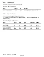
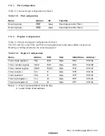
Table 13.1 shows the pin configuration of timer J.
Table 13.1
Pin Configuration
Name
Abbrev.
I/O
Function
Event input pin
,54
4
Input
Event inputs to the TMJ-1
Event input pin
,54
5
Input
Event inputs to the TMJ-2
13.1.4
Register Configuration
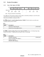
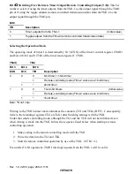
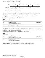
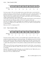
Table 13.2 shows the register configuration of timer J.
The TCJ and TLJ or the TCK and TLK are being allocated to the same address respectively.
Reading or writing determines the accessing register.
Table 13.2
Register Configuration
Name
Abbrev.
R/W
Size
Initial Value
Address
*2
Timer mode register J
TMJ
R/W
Byte
H'00
H'D13A
Timer J control register
TMJC
R/W
Byte
H'09
H'D13B
Timer J status register
TMJS
R/(W)
*1
Byte
H'3F
H'D13C
Timer counter J
TCJ
R
Byte
H'FF
H'D139
Timer counter K
TCK
R
Byte
H'FF
H'D138
Timer load register J
TLJ
W
Byte
H'FF
H'D139
Timer load register K
TLK
W
Byte
H'FF
H'D138
Notes: 1. Only 0 can be written to clear the flag.
2. Lower 16 bits of the address.

