Rev. 1.0, 02/00, page 694 of 1141
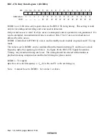
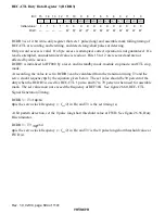
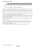
REC-CTL Duty Data Register 3 (RCDR3)
1
1
1
1
13
14
15
1
0
3
2
5
4
7
6
9
8
11
10
CMT31
W
12
—
—
—
—
—
—
—
—
0
CMT30
W
0
CMT33
W
0
CMT32
W
0
CMT35
W
0
CMT34
W
0
CMT37
W
0
CMT36
W
0
CMT39
W
0
CMT38
W
0
CMT3B
W
0
CMT3A
W
0
Bit :
Initial value :
R/W :
RCDR3 is a 12-bit write-only register that sets 1 pulse (long) and assemble mark falling timing of
REC-CTL at recording and rewriting, and detects long/short pulses at detecting.
Only a word access is valid. If a byte access is attempted, correct operation is not guaranteed. If a
read is attempted, an undetermined value is read out. Bits 15 to 12 are reserved and are not
affected by write access.
RCDR3 is initialized to H'F000 by a reset, and in standby mode, module stop mode, and CTL stop
mode.
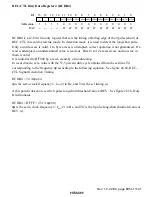
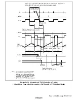
At recording, the value to set in RCDR3 can be calculated from the transition timing T3 and the
servo clock frequency
φ
s by the equation given below. The set value should be 30 percent of the
duty when the RCDR3 is used for REC-CTL 1 pulse, and 67 to 70 percent when used for assemble
mark. The set value must not exceed the frequency of REF30X. See figure 26.60, REC-CTL
Signal Generation Timing.
RCDR3 = T3
×
φ
s/64
φ
s is the servo clock frequency (= f
OSC
/2) in Hz, and T3 is the set timing (s).
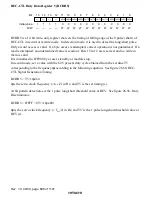
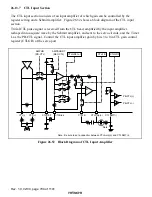
At bit pattern detection, set the 0 pulse long/short threshold value at FWD. See figure 26.56, Duty
Discriminator.
RCDR3 = T3'
×
φ
s/64
φ
s is the servo clock frequency (= f
OSC
/2) in Hz, and T3' is the 0 pulse long/short threshold value at
FWD (s).

