Rev. 1.0, 02/00, page 740 of 1141
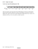
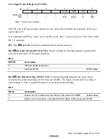
Noise Detection Window Setting Register (NWR)
0
0
1
0
W
2
0
W
3
0
4
0
W
5
0
6
1
7
—
—
—
—
W
W
W
NWR5
NWR4
NWR3
NWR2
NWR1
NWR0
1
Bit :
Initial value :
R/W :
NWR is an 8-bit write-only register that sets the period (window) when the drop-out of the
horizontal sync signal pulse is detected and the noise is counted. Set the timing of the noise
detection window in bits 5 to 0. Bits 7 and 6 are reserved.
If a read is attempted, an undetermined value is read out. It is initialized to H'C0 by a reset, or in
stand-by or module stop mode.
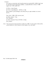
Set the value of the noise detection window timing according to the following equation.
((Value of NWR5-0) + 1)
×
2/
φ
s = 1/4
×
TH
Where, TH is the pulse width of the horizontal sync signal (
µ
s), and
φ
s is the servo clock (fosc/2).
It is recommended that this timing value is set at about 1/4 of the cycle of the horizontal sync
signal.
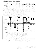
Noise Detection Register (NDR)
0
0
1
0
W
2
0
W
3
0
4
0
W
0
W
5
6
0
7
NDR4
NDR3
NDR2
NDR1
NDR0
0
W
NDR7
W
W
W
NDR6
NDR5
Bit :
Initial value :
R/W :
NDR is an 8-bit write-only register that sets the noise detection level when the noise of the
horizontal sync signal is detected (when NWR is set). Set the noise detection level in bits 7 to 0.
No read is valid. If a read is attempted, an undetermined value is read out. It is initialized to H'00
by a reset, or in stand-by or module stop mode.
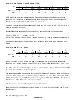
The noise detector takes counts of the drop-outs of the horizontal sync signal pulses and the noise
within the pulses, and if they amount to a count greater than four times of the value set in NDR7-
NDR0, the detector sets the NOIS flag in the sync signal control register (SYNCR). Set the noise
detection level at 1/4 of the noise counts in one frame.
The noise counter is cleared whenever Vsync is detected twice.
See section 26.15.6, Noise Detection for the details of the noise detection window and the noise
detection level.


