Rev. 1.0, 02/00, page 739 of 1141
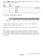
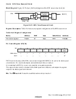
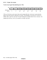
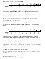
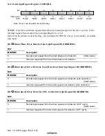
H Complement Start Time Setting Register (HRTR)
0
0
1
0
W
2
0
W
3
0
4
0
W
0
W
5
6
0
7
HRTR4
HRTR3
HRTR2
HRTR1
HRTR0
0
W
HRTR7
W
W
W
HRTR6
HRTR5
Bit :
Initial value :
R/W :
HRTR is an 8-bit write-only register that sets the timing to generate a complementary pulse if a
pulse of the horizontal sync signal is missing.
If a read is attempted, an undetermined value is read out. It is initialized to H'00 by a reset, or in
stand-by or module stop mode.
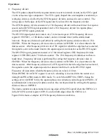
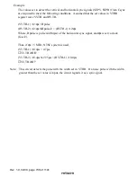
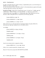
((Value of HRTR7-0) + 1)
×
2/
φ
s = TH
where, TH is the period of the horizontal sync signal (
µ
s), and
φ
s is the servo clock (fosc/2).
Whether the horizontal sync signal exists or not is determined one clock before the
complementary pulse is generated. Accordingly, set to HRTR7 to HRTR0 a value obtained from
the equation shown above plus one.
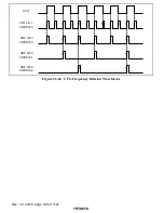
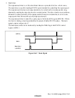
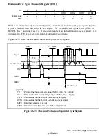
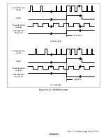
Also, HRTR7-HRTR0 sets the noise mask period. If the horizontal sync signal has the normal
pulses, it is masked in the mask period.
The start and the end of the mask period are computed frm the rising edge of OSCH and SEPH,
respectively. See figure 26.75.
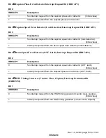
Complementary H Pulse Width Setting Register (HPWR)
0
0
1
0
W
2
0
W
3
0
4
5
6
1
7
—
—
—
—
—
—
—
—
W
W
HPWR3
HPWR2
HPWR1
HPWR0
1
1
1
Bit :
Initial value :
R/W :
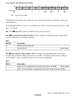
HRWR is an 8-bit write-only register that sets the pulse width of the complementary pulse which
is generated if a pulse of the horizontal sync signal is missing. Bits 7 to 4 are reserved.
If a read is attempted, an undetermined value is read out. It is initialized to H'F0 by a reset or in
stand-by mode.
((Value of HPWR3-0) + 1)
×
2/
φ
s = Hpulse
Where, Hpuls is the pulse width of the horizontal sync signal (
µ
s), and
φ
s is the servo clock
(fosc/2).

