Rev. 1.0, 02/00, page 277 of 1141
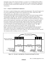
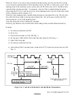
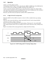
When the Timer J is set to the remote controlled operation mode, since the start bit (ST) is being
set or cleared in synchronization with the inputting clock to the TMJ-2, a delay upto a cycle of the
inputting clock at the maximum occurs, namely, after the ST bit has been set to 1 until the remote
controlled data transmission starts. Consequently, when the TLK is updated during the period
after setting the ST bit to 1 until the next cycle of the inputting clock comes, the initial burst width
will be changed as shown in figure 13.4.
Therefore, when making remote controlled data transmission, determine I/O of the TGL bit at the
time of the first burst width control operation without fail. (Or, set the space width to the TLK
after waiting for a cycle of the inputting clock.)
After that, operations can be continued by interrupts.
Similarly, pay attention to the control works when ending remote controlled data transmission.
Example:
1) Set the burst width with the TLK.
2) ST bit
←
1.
3) Execute the procedure 4) if the TGL flag = 1.
4) Set the space width with the TLK under the status where the TGL flag = 1.
5) Make TMJ-2 interrupt.
6) Set the burst width with the TLK.
:
n) After making TMJ-2 interrupt, make setting of the ST
←
0 under the status where the TGL
flag = 0.
The period during which the
space width settig can be
made. (S)
Delay
Interrupt
Interrupt
TLK setting
(Burst width)
(B)
Burst width
according to (B)
Space width
according to (S)
Stopping the remote controlled
data transmission
TGL flag
Inputting clock
to the TMJ-2
ST
←
0
Delay
ST
←
1
Remote controlled data
transmission starts here.
If an updating is made with the
TLK during this period, the burst
width will be changed.
Figure 13.4 Controls of the Remote Controlled Data Transmission

