Rev. 1.0, 02/00, page 707 of 1141
26.13.8
Duty Discriminator
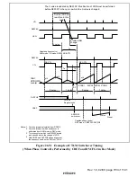
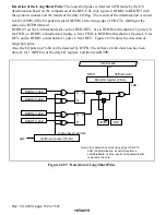
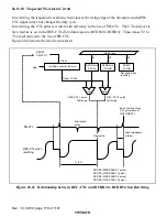
The duty discriminator circuit measures the period of the control signal recorded on the tape (PB-
CTL signal) and discriminates its duty cycle. In VISS or VASS detection, the duty I/O flag is set
or cleared according to the result of duty discrimination. The duty I/O flag is set to 1 when the
duty cycle of the PB-CTL signal is above 44%, and is cleared to 0 when the duty cycle is below
44%.
In ASM detection, an ASM mark is recognized (and the duty I/O flag is cleared to 0) when the
duty cycle is above 66%. When the duty cycle is below 66%, no ASM mark is recognized and the
duty I/O flag is set to 1.
The detection direction can be switched between forward and reverse by bit 5 (FW/RV) in the
CTL mode register.
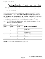
Long or short pulse can be detected by comparing REC-CTL duty data register (RCDR2 to
RCDR5) and UP/DOWN counter. Long or short pulse is discriminated at PB-CTL signal falling.
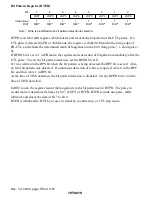
Discrimination result is stored in bit 0 of bit pattern register (BTPR). At the same time, BTPR is
shifted to the left. LSP0 indicates 0 when short pulse is detected, and 1 when long pulse is
detected.
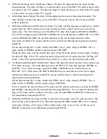
Set the threshold value of long/short pulse in RCDR2 to RCDR5. See the description on the
detection of the long/short pulse.
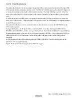
Figure 26.55 shows the duty cycle of the PB-CTL signal.

