Rev. 1.0, 02/00, page 1057 of 1141
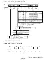
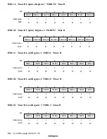
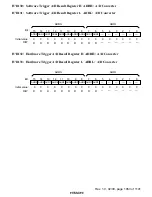
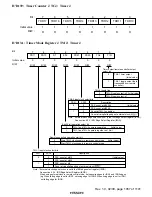
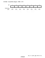
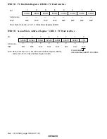
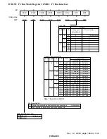
H'D139: Timer Counter J TCJ: Timer J
0
1
1
1
R
2
1
R
3
1
4
1
R
5
1
6
1
7
R
R
R
TDR15
R
TDR16
1
R
TDR17
TDR14
TDR13
TDR12
TDR11
TDR10
Bit :
Initial value :
R/W :
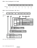
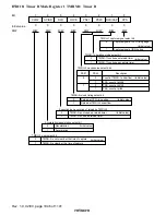
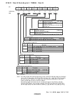
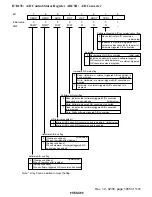
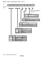
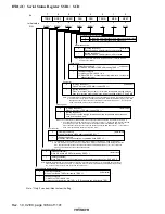
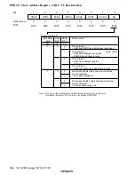
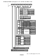
H'D13A: Timer Mode Register J TMJ: Timer J
0
0
1
0
R
2
0
R/W
3
0
4
0
R/W
5
0
6
0
7
R/W
R/W
R/W
ST
R/W
PS10
0
R/W
PS11
8/16
PS21
PS20
TGL
T/R
TMJ-2 toggle flag
TMJ-2 toggle output is 0 (Initial value)
TMJ-2 toggle output is 1
0
1
Timer output/remote-controller output
select bit
TMJ-1 timer output
(Initial value)
TMJ-1 toggle output (data
transmitted from remote
controller)
0
1
TMJ-1 and TMJ-2 operate separately
(Initial value)
TMJ-1 and TMJ-2 operate together as 16-bit
0
1
8-bit/16-bit operation select bit
Stop TMJ-1 clock supply in remote control mode
(Initial value)
Start TMJ-1 clock supply in remote control mode
0
1
Remote-controlled operation start bit
Note: * External clock edge selection is set in the IRQ edge select register (IEGR).
See section 6.2.4, IRQ Edge Select Register (IEGR).
When using external clock in remote control mode, set opposite edges for IRQ1 and IRQ2 edges
(eg. When falling edge is set for IRQ1, set rising edge for IRQ2. When rising edge is set for IRQ1,
set falling edge for IRQ2).
0
0
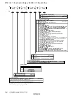
PS10
PS11
1
0
1
PSS, count at
φ
/512
(Initial value)
PSS, count at
φ
/256
PSS, count at
φ
/4
1
Count at rising/falling edge of external clock (
)*
TMJ-1 input clock select bits
Description
Note: * External clock edge selection is set in the IRQ edge select register (IEGR).
See section 6.2.4, IRQ Edge Select Register (IEGR).
0
0
PS20
PS21
1
0
1
PSS, count at
φ
/16384
(Initial value)
PSS, count at
φ
/2048
Count at TMJ-1 underflow
1
Count at rising/falling edge of external clock (
) *
TMJ-2 input clock select bits
Description
Initial value :
Bit
R/W
:
:

