Rev. 1.0, 02/00, page 815 of 1141
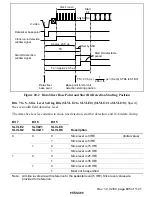
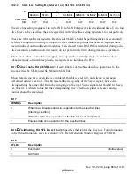
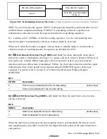
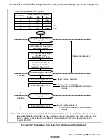
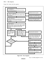
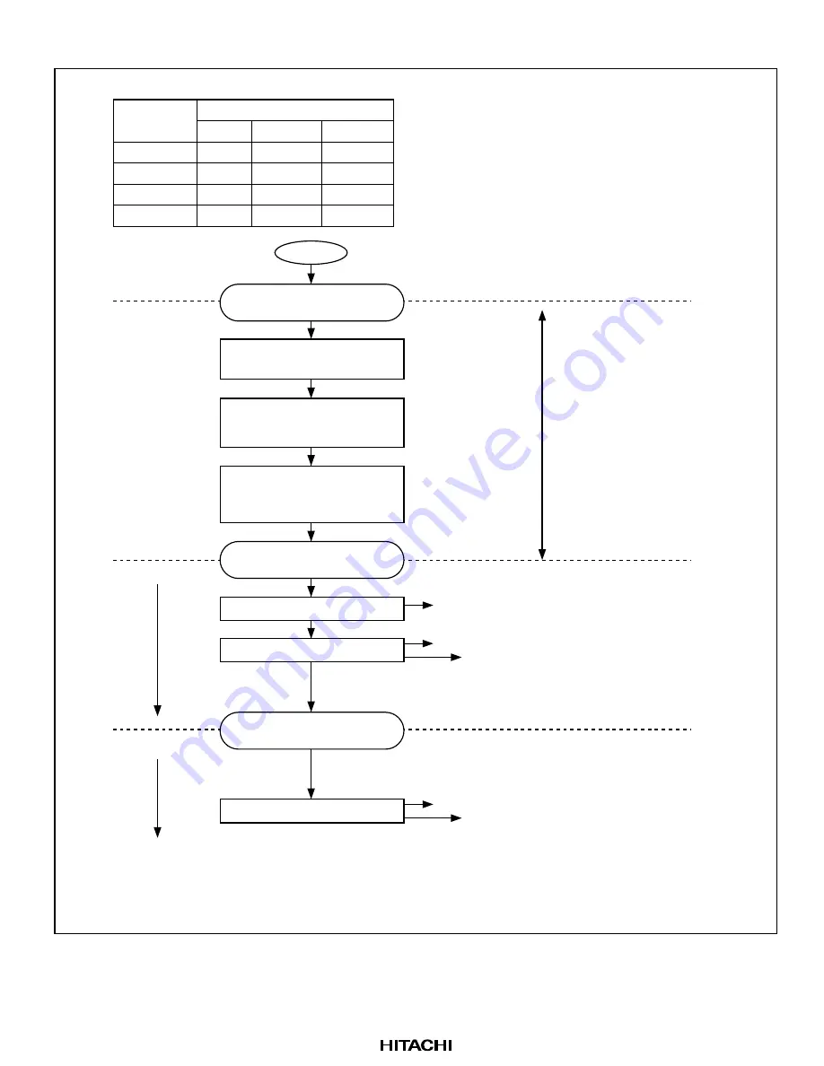
The data slicer initialization and operation for one specification example are shown in figure 28.9.
Reset the slice enable bit
Reset the slice enable bit
Generate an even field slice completion
interrupt
Contents of slice line setting registers
Slice Line Setting Register
Register No.
1
2
3
4
1
1
1
0
Even
Odd
Even
d > c
b > a
Odd
Enable Field
Line
Start
Initialize the data slicer
Reset the slice enable bit
Generate an odd field slice completion
interrupt
Even field
Odd field
Line c
Line b
Line d
Line a
Set the slice (even and odd)
field mode registers
Set the slice line setting
registers 1 to 4
(except the enable bits)
An external Vsync interrupt
occurs
Execute slicing for line b
An external Vsync interrupt
occurs
Execute slicing for line d
Execute slicing for line c
An external Vsync interrupt
occurs
Set the enable bits of
the slice line setting
registers 1 through 3 to 1
Note: Data slice operation is not performed for line a, because the enable bit = 0. Further, when the same line
is specified within the same field, erroneous operation results; do not specify the same line in the same
field. For details on the external Vsync interrupt, refer to section 27.2.2, Sync Separation Control
Register (SEPCR).
Figure 28.9 Example of Slice Line Specification and Operation (1)

