Rev. 1.0, 02/00, page 349 of 1141
17.1.3
Register Configuration
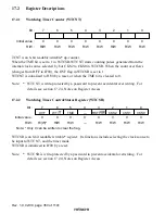
The WDT has two registers, as described in table 17.1. These registers control clock selection,
WDT mode switching, the reset signal, etc.
Table 17.1
WDT Registers
Address
*1
Name
Abbrev.
R/W
Initial Value
Write
*2
Read
Watchdog timer
control/status register
WTCSR
R/ (W)
*3
H'00
H'FFBC
H'FFBC
Watchdog timer counter
WTCNT
R/W
H'00
H'FFBC
H'FFBD
System control register
SYSCR
R/W
H'09
H'FFE8
H'FFE8
Notes: 1. Lower 16 bits of the address.
2. For details of write operations, see section 17.2.4, Notes on Register Access.
3. Only 0 can be written in bit 7, to clear the flag.

