Rev. 1.0, 02/00, page 332 of 1141
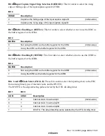
Bit 0
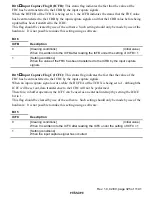
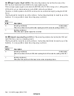
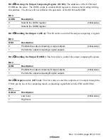
Output Level B (OLVLB): This bit works to select the output level to output through the
FTOB pin by use of the comparing match B (matching signal between the FRC and OCRB).
Bit 0
OLVLB
Description
0
Low level
(Initial value)
1
High level
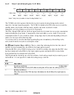
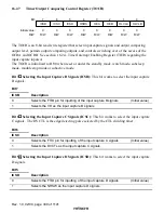
16.2.8
Module Stop Control Register (MSTPCR)
7
0
MSTP15
R/W
MSTPCRH
6
0
MSTP14
R/W
5
1
MSTP13
R/W
4
1
MSTP12
R/W
3
1
MSTP11
R/W
2
1
MSTP10
R/W
1
1
MSTP9
R/W
0
1
MSTP8
R/W
7
1
MSTP7
R/W
6
1
MSTP6
R/W
5
1
MSTP5
R/W
4
1
MSTP4
R/W
3
1
MSTP3
R/W
2
1
MSTP2
R/W
1
1
MSTP1
R/W
0
1
MSTP0
R/W
MSTPCRL
Initial value :
R/W :
Bit :
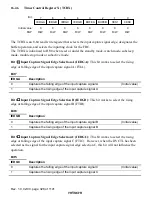
The MSTPCR consists of twin 8-bit read/write registers that control the module stop mode.
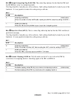
When the MSTP10 bit is set to 1, the Timer X1 stops its operation at the ending point of the bus
cycle to shift to the module stop mode. For more information, see section 4.5, Module Stop
Mode.
When reset, the MSTPCR is initialized to H'FFFF.
Bit 2
Module Stop (MSTP10): This bit works to designate the module stop mode for timer X1.
MSTPCRH
Bit 2
MSTP10
Description
0
Cancels the module stop mode of the Timer X1
1
Sets the module stop mode of the Timer X1
(Initial value)

