Rev. 1.0, 02/00, page 809 of 1141
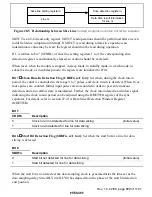
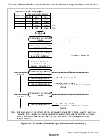
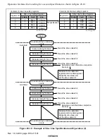
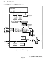
Slice line setting register n
Line m
Slice detection register n
Data slice result information
for line m
Figure 28.5 Relationship between Slice Line
Setting R egister and Slice D etection R egister
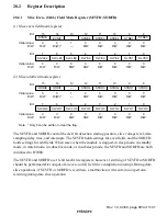
SDTCT is an 8-bit read-only register. SDTCT read operations should be performed after an even
(odd) field slice completion interrupt. If SDTCT is read during a data slice operation, an
indeterminate value may be read; the register should not be read during operation.
If 1 is written to bit 7 (SENBL) of slice line setting registers 1 to 4, the corresponding slice
detection register is automatically cleared, so caution should be exercised.
When reset, when the module is stopped, in sleep mode, in standby mode, in watch mode, in
subactive mode, or in subsleep mode, the registers are initialized to H'10.
Bit 7
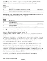
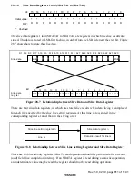
Clock Run-In Detection Flag (CRDFn n=1 to 4): Set when, during the clock run-in
period, the count is concluded in the range 3 to 7 pulses, and clock run-in is detected. When 16 or
more pulses are counted, further input pulses are not counted in order to prevent erroneous
detection, and an overflow state is maintained. Further, the clock run-in detection window signal
indicating the clock run-in period can be adjusted using the DDETWR register of the sync
separator. For details, refer to section 27.2.10, Data Slicer Detection Window Register
(DDETWR).
Bit 7
CRDFn
Description
0
Clock run-in not detected for line for data slicing
(Initial value)
1
Clock run-in detected for line for data slicing
Bit 6
Start Bit Detection Flag (SBDFn, n=1 to 4): Set when the start bit for a line for data
slicing is detected.
Bit 6
SBDFn
Description
0
Start bit not detected for line for data slicing
(Initial value)
1
Start bit detected for line for data slicing
When the start bit is not detected, the data sampling clock is generated after the time set as the
data sampling delay time (DLY4 to DLY0) has elapsed from the phase of the start bit detection
end position.

