Rev. 1.0, 02/00, page 194 of 1141
Bit 7
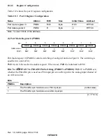
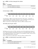
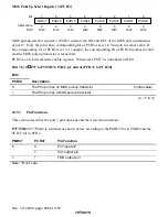
P17/TMOW Pin Switching (PMR17): PMR17 sets whether the P17/TMOW pin is used
as a P17 I/O pin or a TMOW pin for the frequency division clock output.
Bit 7
PMR17
Description
0
The P17/TMOW pin functions as a P17 I/O pin
(Initial value)
1
The P17/TMOW pin functions as a TMOW output pin
Bit 6
P16/
,&
,&
,&
,&
Pin Switching (PMR16): PMR16 sets whether the P16/
,&
pin as a P16 I/O pin or
an
,&
pin for the input capture input of the prescalar unit. The
,&
pin has a built-in noise cancel
circuit. See section 21, Prescalar Unit.
Bit 6
PMR16
Description
0
The P16/
,&
pin functions as a P16 I/O pin
(Initial value)
1
The P16/
,&
pin functions as an
#
,&
input pin
Bits 5 to 0
P15/
,54
8
,54
8
,54
8
,54
8
to P10/
,54
3
,54
3
,54
3
,54
3
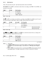
Pin Switching (PMR15 to PMR10): PMR15 to PMR10 set
whether the P1n/
,54Q
pin is used as a P1n I/O pin or an
,54Q
pin for the external interrupt
request input.
Bit n
PMR1n
Description
0
The P1n/
,54Q
pin functions as a P1n I/O pin
(Initial value)
1
The P1n/
,54Q
pin functions as an
,54Q
input pin
(n = 5 to 0)
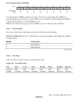
Port Control Register 1 (PCR1)
0
0
1
0
W
2
0
W
3
0
4
0
W
0
W
5
0
7
0
W
W
W
W
6
PCR14
PCR13
PCR12
PCR11
PCR10
PCR17
PCR16
PCR15
Bit :
Initial value :
R/W :
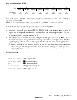
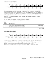
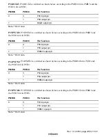
Port control register 1 (PCR1) controls the I/Os of pins P17 to P10 of port 1 in a unit of bit.
When PCR1 is set to 1, the corresponding P17 to P10 pins become output pins, and when it is set
to 0, they become input pins. When the relevant pin is set to a general I/O by PMR1, settings of
PCR1 and PDR1 become valid.
PCR1 is an 8-bit write-only register. When PCR1 is read, 1 is read. When reset, PCR1 is
initialized to H'00.

