Rev. 1.0, 02/00, page 808 of 1141
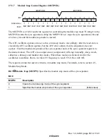
Bit 5
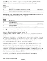
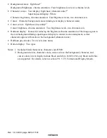
Reserved: Cannot be modified and is always read as 1.
Bits 4 to 0
Slice Line Setting Bits (SLINE4 to SLINE0): Specify the data slice line. Slice lines
up to H'1F (31) can be specified.
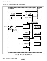
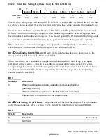
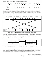
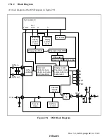
Figure 28.4 explains the line count.
9-line vertical sync pulse period
Pre-equalizing
period
Sync separation
base point
0
1
1
2
3
4
5
6
7
8
9
10
19
20
21
H'11
2
3
4
5
6
15
16
17
18
Line count
Clear
Post-equalizing
period
Vertical synchro-
nization period
Line count specified by
SLINEn4 to SLINEn0
(n = 1 to 4)
Figure 28.4 Line Count
28.2.3
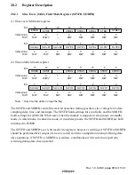
Slice Detection Registers 1 to 4 (SDTCT1 to SDTCT4)
0
0
1
0
R
2
0
R
3
0
4
1
—
0
R
5
6
0
7
—
CRICn3
CRICn2
CRICn1
CRICn0
0
R
CRDFn
R
R
R
SBDFn
ENDFn
Bit:
Initial value:
R/W:
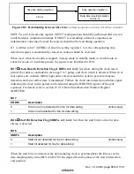
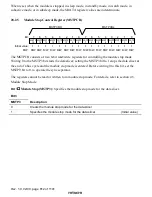
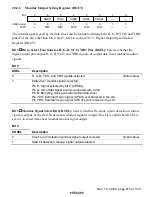
The slice detection registers 1 to 4 (SDTCT1 to SDTCT4) store information on data slice results.
Data slice result information includes the clock run-in detection flag, start bit detection flag, data
end detection flag, and run-in pulse count for the clock run-in period.
This information is useful for optimal positioning of the data slicer slice level, start bit detection
timing, and sampling clock generation timing.
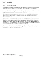
There are four slice detection registers; data slice information results are stored in them on
completion of data slicing for each line specified by the slice line setting registers 1 to 4. Data is
stored not in slicing order, but in the corresponding registers. For information on the slice line
sequence, refer to section 28.3.2, Slice Sequence.

