Rev. 1.0, 02/00, page 1017 of 1141
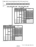
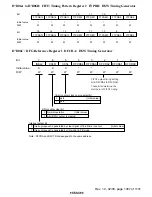
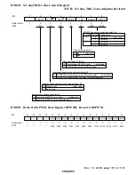
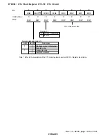
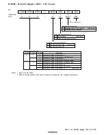
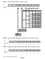
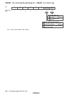
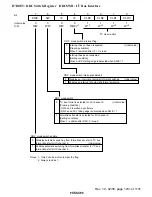
H'D08C: Duty I/O Register DI/O: CTL Circuit
0
1
1
0
R/(W)*
1
2
0
W
3
0
4
5
1
6
7
R/W
W
W
VCTR0
1
W
VCTR1
1
W
VCTR2
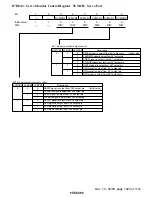
BPON
BPS
BPF
DI/O
1
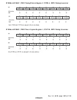
Notes: 1. Only 0 can be written.
2. Refer to the description of the duty I/O register in section 26.13.5, Register Description.
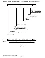
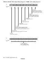
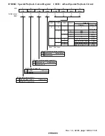
Bit pattern detection ON/OFF bit
0 Bit pattern detection OFF
(initial value)
1 Bit pattern detection ON
Bit pattern detection start bit
0 Normal status
(initial value)
1 Starts 8-bit bit pattern detection
Duty I/O register
*
2
Bit pattern detection flag
0 Bit pattern (8-bit) is not detected
(initial value)
1 Bit pattern (8-bit) is detected
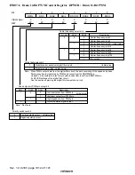
VCTR2 VCTR1 VCTR0
Description
0 0 0 Number of 1-pulse for detection = 2
1 Number of 1-pulse for detection = 4 (SYNC mark)
1 0 Number of 1-pulse for detection = 6
1 Number of 1-pulse for detection = 8 (mark A, short)
1 0 0 Number of 1-pulse for detection = 12 (mark A, long)
1 Number of 1-pulse for detection = 16
1 0 Number of 1-pulse for detection = 24 (mark B)
1 Number of 1-pulse for detection = 32
(initial value)
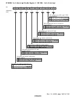
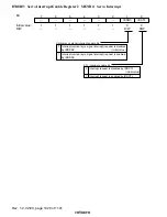
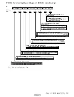
VISS interrupt setting bits
—
—
Bit
Initial value
R/W
:
:
:

