


Appendix - 48
Appendices
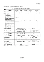
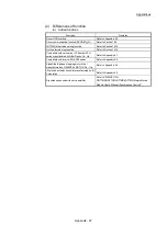
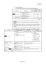
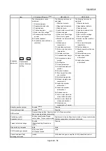
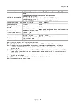
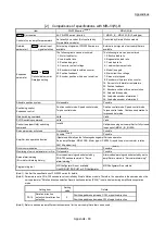
(b) Changed functions
Function Description
Specification
LD77MS2 LD77MS4 LD77MS16 LD77MH4 LD77MH16
Input signal [X0]
Signal name
READY
LD77 READY
Driver communication
function
Function name
Driver communication function
Master-slave operation function
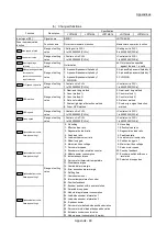
Pr.7
Bias speed at start
Range of setting
value
<Setting unit is PLS>
0 to 1000000000 [PLS/s]
<Setting unit is PLS>
0 to 50000000 [PLS/s]
Pr.8
Speed limit value
Range of setting
value
<Control unit is PLS>
1 to 1000000000 [PLS/s]
<Control unit is PLS>
1 to 50000000 [PLS/s]
Pr.22
Input signal logic
selection
Range of setting
value
No limitation
b4: Only the value specified
against the axis 1 is valid
Pr.24
Manual pulse generator
/Incremental
synchronous encoder
input selection
Range of setting
value
0: A-phase/B-phase multiplied by 4
1: A-phase/B-phase multiplied by 2
2: A-phase/B-phase multiplied by 1
3: PLS/SIGN
0: A-phase/B-phase multiplied by 4
2: A-phase/B-phase multiplied by 1
3: PLS/SIGN
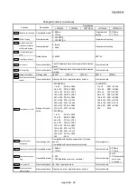
Pr.31
JOG speed limit value
Range of setting
value
<Control unit is PLS>
1 to 1000000000 [PLS/s]
<Control unit is PLS>
1 to 50000000 [PLS/s]
Pr.43
OPR method
Range of setting
value
0: Near-point dog method
4: Count method 1)
5: Count method 2)
6: Data set method
7: Scale origin signal detection method
8: Driver OPR method
0: Near-point dog method
4: Count method 1)
5: Count method 2)
6: Data set method
7: Scale origin signal detection
method
Pr.46
OPR speed
Range of setting
value
<Control unit is PLS>
1 to 1000000000 [PLS/s]
<Control unit is PLS>
1 to 50000000 [PLS/s]
Pr.47
Creep speed
Range of setting
value
<Control unit is PLS>
1 to 1000000000 [PLS/s]
<Control unit is PLS>
1 to 50000000 [PLS/s]
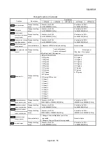
Pr.91
Optional data monitor:
Data type setting 1
Range of setting
value
0: No setting
1: Effective load ratio
2: Regenerative load ratio
3: Peak load ratio
4: Load inertia moment ratio
5: Model loop gain
6: Main circuit bus voltage
7: Servo motor speed
8: Encoder multiple revolution counter
9: Module power consumption
10: Instantaneous torque
12: Servo motor thermistor temperature
13: Disturbance torque
14: Overload alarm margin
15: Error excessive alarm margin
16: Settling time
17: Overshoot amount
18: Internal temperature of encoder
20: Position feedback
21: Encoder position within one revolution
22: Selected droop pulse
23: Module integral power consumption
24: Load-side encoder information 1
25: Load-side encoder information 2
26: Z-phase counter
27: Servo motor side/load-side position deviation
28: Servo motor side /load-side speed deviation
29: External encoder counter value
30: Module power consumption (2 words)
0: No setting
1: Effective load ratio
2: Regenerative load ratio
3: Peak load ratio
4: Load to motor inertia ratio
5: Position loop gain 1
6: Main circuit bus voltage
7: Servo motor speed
20: Position feedback
21: Encoder position within one
revolution
22: Selected droop pulses
Pr.92
Optional data monitor:
Data type setting 2
Pr.93
Optional data monitor:
Data type setting 3
Pr.94
Optional data monitor:
Data type setting 4
Summary of Contents for MELSEC-L Series
Page 2: ......
Page 30: ...MEMO ...
Page 70: ...2 10 Chapter 2 System Configuration MEMO ...
Page 83: ...3 13 Chapter 3 Specifications and Functions MEMO ...
Page 103: ...3 33 Chapter 3 Specifications and Functions MEMO ...
Page 107: ...3 37 Chapter 3 Specifications and Functions MEMO ...
Page 111: ...3 41 Chapter 3 Specifications and Functions MEMO ...
Page 115: ...3 45 Chapter 3 Specifications and Functions MEMO ...
Page 140: ...4 22 Chapter 4 Installation Wiring and Maintenance of the Product MEMO ...
Page 253: ...5 113 Chapter 5 Data Used for Positioning Control MEMO ...
Page 342: ...5 202 Chapter 5 Data Used for Positioning Control MEMO ...
Page 438: ...7 20 Chapter 7 Memory Configuration and Data Process MEMO ...
Page 440: ...MEMO ...
Page 485: ...9 25 Chapter 9 Major Positioning Control MEMO ...
Page 594: ...9 134 Chapter 9 Major Positioning Control MEMO ...
Page 624: ...10 30 Chapter 10 High Level Positioning Control MEMO ...
Page 656: ...11 32 Chapter 11 Manual Control MEMO ...
Page 690: ...12 34 Chapter 12 Expansion Control MEMO ...
Page 798: ...13 108 Chapter 13 Control Sub Functions MEMO ...
Page 866: ...14 68 Chapter 14 Common Functions MEMO ...
Page 884: ...15 18 Chapter 15 Dedicated Instructions MEMO ...
Page 899: ...16 15 Chapter 16 Troubleshooting MEMO ...
Page 1036: ...Appendix 88 Appendices MEMO ...
Page 1039: ......


