
1 - 21
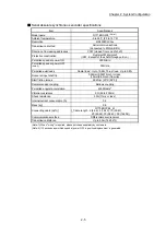
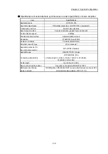
Chapter 1 Product Outline
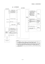
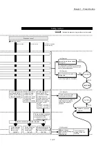
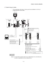
(2) LD77MS16
READY signal
Positioning start signal
BUSY signal
Servo
amplifier
LD77MS16
Y0
Y10 to Y1F
X0
PLC CPU
Manual pulse
generator/
Incremental
synchronous
encoder
Operation monitor
Parameter write/read
JOG operation, inching operation
(Test)
Positioning operation (Test)
OPR operation (Test)
GX Works2
Peripheral
device
interface
X10 to X1F
Synchronization flag
X1
All axis servo ON signal
Y1
Interface
with
PLC CPU
External
interface
PLC READY signal
Data write/read
Positioning data write/read
Block start data write/read
Operating information of
the servo amplifier
Positioning command
Control command
Servo parameter
External input signal of
the servo amplifier
Manual pulse generator/
Incremental synchronous encoder
A-phase
Manual pulse generator/
Incremental synchronous encoder
B-phase
POINT
(1) For LD77MS16, M code ON signal, error detection signal, start complete signal and
positioning complete signal are assigned to the bit of " Status".
(2) For LD77MS16, axis stop signal, forward run JOG start signal, reverse run JOG start
signal, execution prohibition flag are assigned to the buffer memory to .
(3) When using the upper/lower limit signal, stop signal, near-point dog signal of the
external input signal via CPU, use the buffer memory in " External input signal
operation device".
Md.31
Cd.180
Cd.183
Cd.44
Forced stop input signal
External command signal/
Switching signal
External
input signal
SSCNET (/H)
Summary of Contents for MELSEC-L Series
Page 2: ......
Page 30: ...MEMO ...
Page 70: ...2 10 Chapter 2 System Configuration MEMO ...
Page 83: ...3 13 Chapter 3 Specifications and Functions MEMO ...
Page 103: ...3 33 Chapter 3 Specifications and Functions MEMO ...
Page 107: ...3 37 Chapter 3 Specifications and Functions MEMO ...
Page 111: ...3 41 Chapter 3 Specifications and Functions MEMO ...
Page 115: ...3 45 Chapter 3 Specifications and Functions MEMO ...
Page 140: ...4 22 Chapter 4 Installation Wiring and Maintenance of the Product MEMO ...
Page 253: ...5 113 Chapter 5 Data Used for Positioning Control MEMO ...
Page 342: ...5 202 Chapter 5 Data Used for Positioning Control MEMO ...
Page 438: ...7 20 Chapter 7 Memory Configuration and Data Process MEMO ...
Page 440: ...MEMO ...
Page 485: ...9 25 Chapter 9 Major Positioning Control MEMO ...
Page 594: ...9 134 Chapter 9 Major Positioning Control MEMO ...
Page 624: ...10 30 Chapter 10 High Level Positioning Control MEMO ...
Page 656: ...11 32 Chapter 11 Manual Control MEMO ...
Page 690: ...12 34 Chapter 12 Expansion Control MEMO ...
Page 798: ...13 108 Chapter 13 Control Sub Functions MEMO ...
Page 866: ...14 68 Chapter 14 Common Functions MEMO ...
Page 884: ...15 18 Chapter 15 Dedicated Instructions MEMO ...
Page 899: ...16 15 Chapter 16 Troubleshooting MEMO ...
Page 1036: ...Appendix 88 Appendices MEMO ...
Page 1039: ......


