


5 - 99
Chapter 5 Data Used for Positioning Control
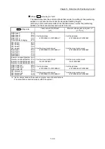
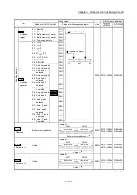
5.4 List of block start data
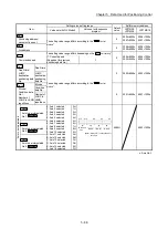
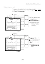
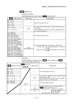
The illustrations below show the organization of the block start data stored in the buffer
memory of Simple Motion module. The block start data setting items
Da.11
to
Da.14
are explained in the pages that follow.
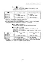
• LD77MS2/ LD77MS4
26049+1000n
26099+1000n
50th point
Setting item
Buffer memory
address
26001+1000n
26051+1000n
2nd point
Setting item
Buffer memory
address
n: Axis No.-1
26000+1000n
26050+1000n
S
tart
bl
oc
k 0
1st point
Setting item
Buffer memory
address
Da.11 Shape
Da.12 Start data No.
Da.14 Parameter
Da.13 Special start instruction
b0
b7
b8
b15
b0
b7
b8
b15
Up to 50 block start data points can be set
(stored) for each axis in the buffer memory
addresses shown on the left.
Items in a single unit of block start data are
shown included in a bold frame.
Each axis has five start blocks (block Nos.
0 to 4).
(Note): For information on the organization
of the buffer memory addresses
assigned to the start blocks 1 to 4,
refer to Appendix 1 "List of buffer
memory addresses".
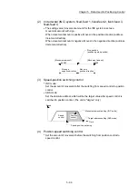
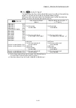
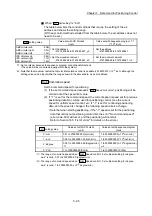
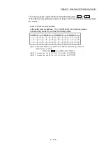
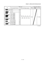
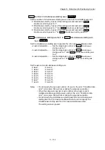
• LD77MS16
22049+400n
22099+400n
50th point
Setting item
Buffer memory
address
22001+400n
22051+400n
2nd point
Setting item
Buffer memory
address
n: Axis No.-1
22000+400n
22050+400n
S
tart
bl
oc
k 0
1st point
Setting item
Buffer memory
address
Da.11 Shape
Da.12 Start data No.
Da.14 Parameter
Da.13 Special start instruction
b0
b7
b8
b15
b0
b7
b8
b15
Up to 50 block start data points can be set
(stored) for each axis in the buffer memory
addresses shown on the left.
Items in a single unit of block start data are
shown included in a bold frame.
Each axis has five start blocks (block Nos.
0 to 4).
Start block 2 to 4 are not allocated to buffer
memory.
Set with GX Works2.
(Note): For information on the organization
of the buffer memory addresses
assigned to the start block 1, refer
to Appendix 1 "List of buffer memory
addresses".
Summary of Contents for MELSEC-L Series
Page 2: ......
Page 30: ...MEMO ...
Page 70: ...2 10 Chapter 2 System Configuration MEMO ...
Page 83: ...3 13 Chapter 3 Specifications and Functions MEMO ...
Page 103: ...3 33 Chapter 3 Specifications and Functions MEMO ...
Page 107: ...3 37 Chapter 3 Specifications and Functions MEMO ...
Page 111: ...3 41 Chapter 3 Specifications and Functions MEMO ...
Page 115: ...3 45 Chapter 3 Specifications and Functions MEMO ...
Page 140: ...4 22 Chapter 4 Installation Wiring and Maintenance of the Product MEMO ...
Page 253: ...5 113 Chapter 5 Data Used for Positioning Control MEMO ...
Page 342: ...5 202 Chapter 5 Data Used for Positioning Control MEMO ...
Page 438: ...7 20 Chapter 7 Memory Configuration and Data Process MEMO ...
Page 440: ...MEMO ...
Page 485: ...9 25 Chapter 9 Major Positioning Control MEMO ...
Page 594: ...9 134 Chapter 9 Major Positioning Control MEMO ...
Page 624: ...10 30 Chapter 10 High Level Positioning Control MEMO ...
Page 656: ...11 32 Chapter 11 Manual Control MEMO ...
Page 690: ...12 34 Chapter 12 Expansion Control MEMO ...
Page 798: ...13 108 Chapter 13 Control Sub Functions MEMO ...
Page 866: ...14 68 Chapter 14 Common Functions MEMO ...
Page 884: ...15 18 Chapter 15 Dedicated Instructions MEMO ...
Page 899: ...16 15 Chapter 16 Troubleshooting MEMO ...
Page 1036: ...Appendix 88 Appendices MEMO ...
Page 1039: ......


