


14 - 33
Chapter 14 Common Functions
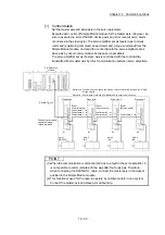
[1] Control details
Set the master axis and slave axis in the servo parameter.
Execute each control of Simple Motion module for the master axis. (However, be
sure to execute the servo ON/OFF of slave axis and error reset at servo alarm
occurrence in the slave axis.) The servo amplifier set as master axis receives
command (positioning command, speed command, torque command) from the
Simple Motion module, and send the control data to the servo amplifier set as
slave axis by driver communication between servo amplifiers.
The servo amplifier set as the slave axis is controlled with the control data
transmitted from master axis by driver communication between servo amplifiers.
Simple Motion
module
d2
d1
Axis 1
ABS/INC
Axis 2
INC
d3
d4
Axis 3
INC
Axis 4
INC
Positioning command/
speed command/
torque command
[Driver
communication]
Control data 1
Control data 2
Control data 3
[Driver
communication]
Control data 2
Control data 3
[Driver
communication]
Control data 3
Master axis
Slave axis 1
Slave axis 2
Slave axis 3
Master axis: Position command, speed command or torque command is received from Simple
Motion module.
Slave axis : Control data is received from Master axis by driver communication.
SSCNET (/H)
POINT
(1) When the communication is disconnected due to a fault in the servo amplifier, it
is not possible to communicate with the axis after the faulty axis. Therefore,
when connecting the SSCNET cable, connect the master axis in the closest
position to the Simple Motion module.
(2) This function is used for the case to operate by multiple motors in one system.
Connect the master axis and slave axis without slip.
Summary of Contents for MELSEC-L Series
Page 2: ......
Page 30: ...MEMO ...
Page 70: ...2 10 Chapter 2 System Configuration MEMO ...
Page 83: ...3 13 Chapter 3 Specifications and Functions MEMO ...
Page 103: ...3 33 Chapter 3 Specifications and Functions MEMO ...
Page 107: ...3 37 Chapter 3 Specifications and Functions MEMO ...
Page 111: ...3 41 Chapter 3 Specifications and Functions MEMO ...
Page 115: ...3 45 Chapter 3 Specifications and Functions MEMO ...
Page 140: ...4 22 Chapter 4 Installation Wiring and Maintenance of the Product MEMO ...
Page 253: ...5 113 Chapter 5 Data Used for Positioning Control MEMO ...
Page 342: ...5 202 Chapter 5 Data Used for Positioning Control MEMO ...
Page 438: ...7 20 Chapter 7 Memory Configuration and Data Process MEMO ...
Page 440: ...MEMO ...
Page 485: ...9 25 Chapter 9 Major Positioning Control MEMO ...
Page 594: ...9 134 Chapter 9 Major Positioning Control MEMO ...
Page 624: ...10 30 Chapter 10 High Level Positioning Control MEMO ...
Page 656: ...11 32 Chapter 11 Manual Control MEMO ...
Page 690: ...12 34 Chapter 12 Expansion Control MEMO ...
Page 798: ...13 108 Chapter 13 Control Sub Functions MEMO ...
Page 866: ...14 68 Chapter 14 Common Functions MEMO ...
Page 884: ...15 18 Chapter 15 Dedicated Instructions MEMO ...
Page 899: ...16 15 Chapter 16 Troubleshooting MEMO ...
Page 1036: ...Appendix 88 Appendices MEMO ...
Page 1039: ......


