


14 - 30
Chapter 14 Common Functions
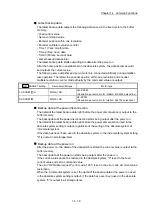
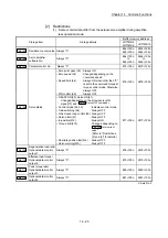
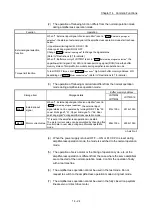
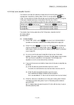
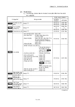
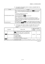
[2] Restrictions
(1) The following monitor data of virtual servo amplifier differ from the actual
servo amplifier.
Storage item
Storage details
Buffer memory address
LD77MS2
LD77MS4
LD77MS16
Md.102
Deviation counter
value
Always "0".
852+100n
853+100n
2452+100n
2453+100n
Md.106
Servo amplifier
software No.
Always "0".
864+100n
to
869+100n
2464+100n
to
2469+100n
Md.107
Parameter error No. Always "0".
870+100n
2470+100n
Md.108
Servo status
• Zero point pass (b0) : Always ON
• Zero speed (b3)
: Changed depending on the
command speed
• Speed limit (b4)
: Always ON when other than "0" is
set to the command torque at
torque control mode. Otherwise,
always OFF.
• PID control (b8)
: Always OFF
876+100n 2476+100n
• READY ON (b0), Servo ON (b1)
: Changed depending on
the all axis servo ON
signal [Y1] and "
Cd.100
Servo OFF command
"
• Control mode (b2, b3)
: Indicates control mode.
• Gain switching (b4)
: Always OFF
• Fully closed loop control (b5) : Always OFF
• Servo alarm (b7)
: Always OFF
• In-position (b12)
: Always ON
• Torque limit (b13)
: Changed depending on
" Md.104 Motor current
value".
(Refer to "Restrictions (2)
and (3)" for details.)
• Absolute position lost (b14) : Always OFF
• Servo warning (b15)
: Always OFF
877+100n 2477+100n
Md.109
Regenerative load
ratio/Optional data
monitor output 1
Always "0".
878+100n
2478+100n
Md.110
Effective load
torque/Optional
data monitor output
2
Always "0".
879+100n
2479+100n
Md.111
Peak torque
ratio/Optional data
monitor output 3
Always "0".
880+100n
2480+100n
Md.112
Optional data
monitor output 4
Always "0".
881+100n
2481+100n
n: Axis No.-1
Summary of Contents for MELSEC-L Series
Page 2: ......
Page 30: ...MEMO ...
Page 70: ...2 10 Chapter 2 System Configuration MEMO ...
Page 83: ...3 13 Chapter 3 Specifications and Functions MEMO ...
Page 103: ...3 33 Chapter 3 Specifications and Functions MEMO ...
Page 107: ...3 37 Chapter 3 Specifications and Functions MEMO ...
Page 111: ...3 41 Chapter 3 Specifications and Functions MEMO ...
Page 115: ...3 45 Chapter 3 Specifications and Functions MEMO ...
Page 140: ...4 22 Chapter 4 Installation Wiring and Maintenance of the Product MEMO ...
Page 253: ...5 113 Chapter 5 Data Used for Positioning Control MEMO ...
Page 342: ...5 202 Chapter 5 Data Used for Positioning Control MEMO ...
Page 438: ...7 20 Chapter 7 Memory Configuration and Data Process MEMO ...
Page 440: ...MEMO ...
Page 485: ...9 25 Chapter 9 Major Positioning Control MEMO ...
Page 594: ...9 134 Chapter 9 Major Positioning Control MEMO ...
Page 624: ...10 30 Chapter 10 High Level Positioning Control MEMO ...
Page 656: ...11 32 Chapter 11 Manual Control MEMO ...
Page 690: ...12 34 Chapter 12 Expansion Control MEMO ...
Page 798: ...13 108 Chapter 13 Control Sub Functions MEMO ...
Page 866: ...14 68 Chapter 14 Common Functions MEMO ...
Page 884: ...15 18 Chapter 15 Dedicated Instructions MEMO ...
Page 899: ...16 15 Chapter 16 Troubleshooting MEMO ...
Page 1036: ...Appendix 88 Appendices MEMO ...
Page 1039: ......


