


13 - 95
Chapter 13 Control Sub Functions
Positioning
Data No.
Da.1
Operation pattern
1
01: Continuous positioning control
2 00:
Positioning
complete
3 00:
Positioning
complete
4
11: Continuous path control
5 00:
Positioning
complete
t
1st point: Continue (1)
3rd point: End (0)
2nd point: Continue (1)
Operation
pattern
Continuous path
control (11)
Positioning
data No. 4
Positioning
data No. 5
Positioning complete (00)
Continuous
positioning
control (01)
Positioning
data No. 1
Positioning
data No. 2
Positioning complete (00)
Positioning
data No. 3
Positioning complete (00)
V
Md.48 Deceleration start flag 0
1
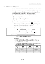
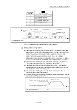
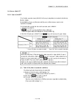
Fig. 13.48 Operation of deceleration start flag at block start
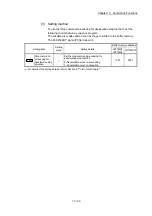
[2] Precautions during control
(1) The deceleration start flag function is valid for the control method of "1-axis
linear control", "2-axis linear interpolation control", "3-axis linear interpolation
control", "4-axis linear interpolation control", "speed-position switching
control" or "position-speed switching control". (In the case of linear
interpolation control, the function is valid for only the reference axis.) Refer to
Section 3.2.5 "Combination of LD77MS main functions and sub functions".
(2) The deceleration start flag does not turn ON when the operation pattern is
"continuous positioning control" or "continuous path control".
(3) The deceleration start flag function is invalid for an OPR, JOG operation,
inching operation, manual pulse generator operation, speed-torque control
and deceleration made with a stop signal.
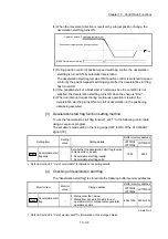
(4) The deceleration start flag does not turn ON when a speed change or
override is used to make deceleration.
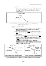
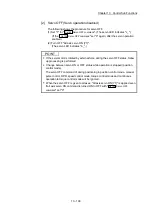
(5) If a target position change is made while the deceleration start flag is ON, the
deceleration start flag remains ON.
Time
Operation pattern: Positioning complete (00)
Md.48 Deceleration start flag 0
1
Deceleration start point
Execution of target position change request
Summary of Contents for MELSEC-L Series
Page 2: ......
Page 30: ...MEMO ...
Page 70: ...2 10 Chapter 2 System Configuration MEMO ...
Page 83: ...3 13 Chapter 3 Specifications and Functions MEMO ...
Page 103: ...3 33 Chapter 3 Specifications and Functions MEMO ...
Page 107: ...3 37 Chapter 3 Specifications and Functions MEMO ...
Page 111: ...3 41 Chapter 3 Specifications and Functions MEMO ...
Page 115: ...3 45 Chapter 3 Specifications and Functions MEMO ...
Page 140: ...4 22 Chapter 4 Installation Wiring and Maintenance of the Product MEMO ...
Page 253: ...5 113 Chapter 5 Data Used for Positioning Control MEMO ...
Page 342: ...5 202 Chapter 5 Data Used for Positioning Control MEMO ...
Page 438: ...7 20 Chapter 7 Memory Configuration and Data Process MEMO ...
Page 440: ...MEMO ...
Page 485: ...9 25 Chapter 9 Major Positioning Control MEMO ...
Page 594: ...9 134 Chapter 9 Major Positioning Control MEMO ...
Page 624: ...10 30 Chapter 10 High Level Positioning Control MEMO ...
Page 656: ...11 32 Chapter 11 Manual Control MEMO ...
Page 690: ...12 34 Chapter 12 Expansion Control MEMO ...
Page 798: ...13 108 Chapter 13 Control Sub Functions MEMO ...
Page 866: ...14 68 Chapter 14 Common Functions MEMO ...
Page 884: ...15 18 Chapter 15 Dedicated Instructions MEMO ...
Page 899: ...16 15 Chapter 16 Troubleshooting MEMO ...
Page 1036: ...Appendix 88 Appendices MEMO ...
Page 1039: ......


