


6 - 72
Chapter 6 Sequence Program Used for Positioning Control
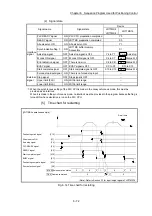
(2) Signal state
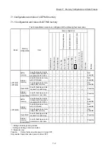
Signal name
Signal state
Device
LD77MS2
LD77MS4
LD77MS16
Interface
signal
PLC READY signal
ON PLC CPU preparation completed
Y0
READY signal
ON LD77MS preparation completed
X0
All axis servo ON
ON All axis servo ON
Y1
Synchronization flag ON
LD77MS buffer memory
Accessible
X1
Axis stop signal
OFF Axis stop signal is OFF
Y4 to Y7
Cd.180
Axis stop
M code ON signal
OFF M code ON signal is OFF
X4 to X7
Md.31
Status: b12
Error detection signal
OFF There is no error
X8 to XB
Md.31
Status: b13
BUSY signal
OFF BUSY signal is OFF
XC to XF
X10 to X1F
Start complete signal
OFF Start complete signal is OFF
X10 to X13
Md.31
Status: b14
External
signal
Forced stop input signal ON There is no forced stop input
–
Stop signal
OFF Stop signal is OFF
–
Upper limit (FLS)
ON Within limit range
–
Lower limit (RLS)
ON Within limit range
–
: When the synchronous setting of the PLC CPU is made in the nonsynchronous mode, this must be
provided as an interlock.
When it is made in the synchronous mode, no interlock must be provided in the program because the flag is
turned ON when calculation is run on the PLC CPU.
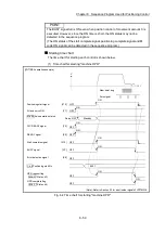
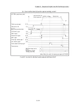
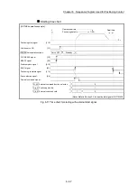
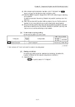
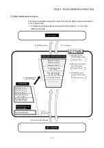
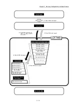
[5] Time chart for restarting
[LD77MS4 operation example]
0
V
t
1
Dwell time
8
1
8
0
0
0
Positioning start signal
Axis stop signal
READY signal
Start complete signal
BUSY signal
Error detection signal
Cd. 6 Restart command
Positioning complete signal
PLC READY signal
Md. 26 Axis operation status
[Y10]
[Y4]
[Y0]
[X0]
[X10]
[XC]
[X14]
[X8]
All axis servo ON
[Y1]
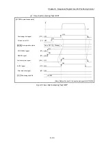
(Note): Refer to Section 3.3 for input/output signal of LD77MS16.
Fig. 6.14 Time chart for restarting
Summary of Contents for MELSEC-L Series
Page 2: ......
Page 30: ...MEMO ...
Page 70: ...2 10 Chapter 2 System Configuration MEMO ...
Page 83: ...3 13 Chapter 3 Specifications and Functions MEMO ...
Page 103: ...3 33 Chapter 3 Specifications and Functions MEMO ...
Page 107: ...3 37 Chapter 3 Specifications and Functions MEMO ...
Page 111: ...3 41 Chapter 3 Specifications and Functions MEMO ...
Page 115: ...3 45 Chapter 3 Specifications and Functions MEMO ...
Page 140: ...4 22 Chapter 4 Installation Wiring and Maintenance of the Product MEMO ...
Page 253: ...5 113 Chapter 5 Data Used for Positioning Control MEMO ...
Page 342: ...5 202 Chapter 5 Data Used for Positioning Control MEMO ...
Page 438: ...7 20 Chapter 7 Memory Configuration and Data Process MEMO ...
Page 440: ...MEMO ...
Page 485: ...9 25 Chapter 9 Major Positioning Control MEMO ...
Page 594: ...9 134 Chapter 9 Major Positioning Control MEMO ...
Page 624: ...10 30 Chapter 10 High Level Positioning Control MEMO ...
Page 656: ...11 32 Chapter 11 Manual Control MEMO ...
Page 690: ...12 34 Chapter 12 Expansion Control MEMO ...
Page 798: ...13 108 Chapter 13 Control Sub Functions MEMO ...
Page 866: ...14 68 Chapter 14 Common Functions MEMO ...
Page 884: ...15 18 Chapter 15 Dedicated Instructions MEMO ...
Page 899: ...16 15 Chapter 16 Troubleshooting MEMO ...
Page 1036: ...Appendix 88 Appendices MEMO ...
Page 1039: ......


