


13 - 5
Chapter 13 Control Sub Functions
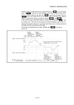
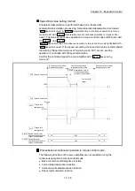
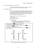
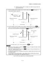
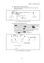
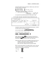
(2) OPR retry operation when the workpiece is outside the range between the
upper and lower limits.
1) When the direction from the workpiece to the OP is the same as the "
Pr.44
OPR direction
", a
normal machine OPR is carried out.
Pr. 44 OPR direction
Hardware upper limit switch
Hardware lower limit switch
Movement range
Machine OPR start
OP
Zero signal
Near-point dog
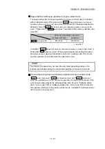
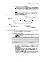
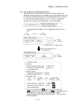
2) When the direction from the workpiece to the OP is the opposite direction from the "
Pr.44
OPR
direction
", the operation carries out a deceleration stop when the near-point dog turns OFF, and
then carries out a machine OPR in the direction set in "
Pr.44
OPR direction
".
Pr. 44 OPR direction
Near-point dog
Hardware upper limit switch
Hardware lower limit switch
Movement range
Machine OPR start
OP
Zero signal
In the a
bove example 1) and 2), "0: Positive direction" is set in
"
Pr.44
OPR direction
"
REMARK
When the "0: Positive direction" is selected in "
Pr.44
OPR direction
", the upper limit switch is set to
the limit switch in the OPR direction.
When the "1: Negative direction" is selected in "
Pr.44
OPR direction
", the lower limit switch is set
to the limit switch in the OPR direction.
If inverting the install positions of upper/lower limit switches, hardware stroke limit function cannot
be operated properly.
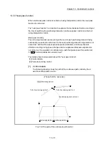
If any problem is found for OPR operation, review "Rotation direction selection/travel direction
selection (PA14)" and the wiring for the upper/lower limit switch.
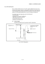
Fig. 13.2 OPR retry operation from on limit (limit signal OFF)
Summary of Contents for MELSEC-L Series
Page 2: ......
Page 30: ...MEMO ...
Page 70: ...2 10 Chapter 2 System Configuration MEMO ...
Page 83: ...3 13 Chapter 3 Specifications and Functions MEMO ...
Page 103: ...3 33 Chapter 3 Specifications and Functions MEMO ...
Page 107: ...3 37 Chapter 3 Specifications and Functions MEMO ...
Page 111: ...3 41 Chapter 3 Specifications and Functions MEMO ...
Page 115: ...3 45 Chapter 3 Specifications and Functions MEMO ...
Page 140: ...4 22 Chapter 4 Installation Wiring and Maintenance of the Product MEMO ...
Page 253: ...5 113 Chapter 5 Data Used for Positioning Control MEMO ...
Page 342: ...5 202 Chapter 5 Data Used for Positioning Control MEMO ...
Page 438: ...7 20 Chapter 7 Memory Configuration and Data Process MEMO ...
Page 440: ...MEMO ...
Page 485: ...9 25 Chapter 9 Major Positioning Control MEMO ...
Page 594: ...9 134 Chapter 9 Major Positioning Control MEMO ...
Page 624: ...10 30 Chapter 10 High Level Positioning Control MEMO ...
Page 656: ...11 32 Chapter 11 Manual Control MEMO ...
Page 690: ...12 34 Chapter 12 Expansion Control MEMO ...
Page 798: ...13 108 Chapter 13 Control Sub Functions MEMO ...
Page 866: ...14 68 Chapter 14 Common Functions MEMO ...
Page 884: ...15 18 Chapter 15 Dedicated Instructions MEMO ...
Page 899: ...16 15 Chapter 16 Troubleshooting MEMO ...
Page 1036: ...Appendix 88 Appendices MEMO ...
Page 1039: ......


