


13 - 78
Chapter 13 Control Sub Functions
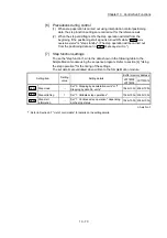
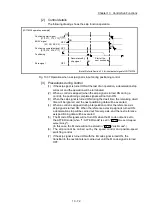
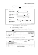
[4] Setting the M code output function
The following shows the settings to use the "M code output function".
(1) Set the M code No. in the positioning data "
Da.10
M code/Condition data
No./Number of LOOP to LEND repetitions
".
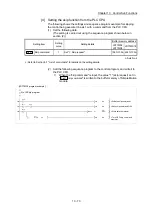
(2) Set the timing to output the M code ON signal.
Set the required value in the following parameter, and write it to the Simple
Motion module.
The set details are validated at the rising edge (OFF
ON) of the PLC READY
signal [Y0].
Setting item
Setting
value
Setting details
Buffer memory address
LD77MS2
LD77MS4
LD77MS16
Pr.18
M code ON signal
output timing
Set the timing to output the M code ON signal.
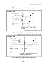
0: WITH mode
1: AFTER mode
27+150n
n: Axis No.-1
: Refer to Section 5.2 "List of parameters" for setting details.
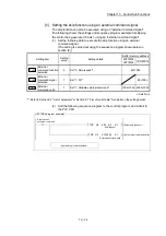
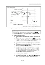
[5] Reading M codes
"M codes" are stored in the following buffer memory when the M code ON signal
turns ON.
Monitor item
Monitor
value
Storage details
Buffer memory address
LD77MS2
LD77MS4
LD77MS16
Md.25
Valid M code
The M code No. (
Da.10
M code/Condition data
No./Number of LOOP to LEND repetitions
) set in
the positioning data is stored.
808+100n 2408+100n
n: Axis No.-1
: Refer to Section 5.6 "List of monitor data" for information on the storage details.
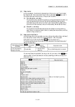
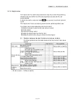
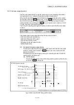
The following shows a sequence program example for reading the "
Md.25
Valid M
code
" to the PLC CPU data register (D110). (The read value is used to command
the sub work.)
Read M codes not as "rising edge commands", but as "ON execution
commands".
M code ON signal
K1
D110
K808
H0
FROM
ON execution command
D110: valid M codes
[LD77MS4 program example]
Summary of Contents for MELSEC-L Series
Page 2: ......
Page 30: ...MEMO ...
Page 70: ...2 10 Chapter 2 System Configuration MEMO ...
Page 83: ...3 13 Chapter 3 Specifications and Functions MEMO ...
Page 103: ...3 33 Chapter 3 Specifications and Functions MEMO ...
Page 107: ...3 37 Chapter 3 Specifications and Functions MEMO ...
Page 111: ...3 41 Chapter 3 Specifications and Functions MEMO ...
Page 115: ...3 45 Chapter 3 Specifications and Functions MEMO ...
Page 140: ...4 22 Chapter 4 Installation Wiring and Maintenance of the Product MEMO ...
Page 253: ...5 113 Chapter 5 Data Used for Positioning Control MEMO ...
Page 342: ...5 202 Chapter 5 Data Used for Positioning Control MEMO ...
Page 438: ...7 20 Chapter 7 Memory Configuration and Data Process MEMO ...
Page 440: ...MEMO ...
Page 485: ...9 25 Chapter 9 Major Positioning Control MEMO ...
Page 594: ...9 134 Chapter 9 Major Positioning Control MEMO ...
Page 624: ...10 30 Chapter 10 High Level Positioning Control MEMO ...
Page 656: ...11 32 Chapter 11 Manual Control MEMO ...
Page 690: ...12 34 Chapter 12 Expansion Control MEMO ...
Page 798: ...13 108 Chapter 13 Control Sub Functions MEMO ...
Page 866: ...14 68 Chapter 14 Common Functions MEMO ...
Page 884: ...15 18 Chapter 15 Dedicated Instructions MEMO ...
Page 899: ...16 15 Chapter 16 Troubleshooting MEMO ...
Page 1036: ...Appendix 88 Appendices MEMO ...
Page 1039: ......


