


16 - 10
Chapter 16 Troubleshooting
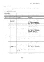
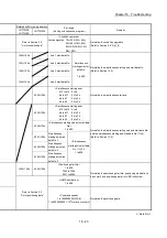
(3) Servo amplifier detection errors
The errors that occur when the hardware error of the servo amplifier or servo
motor or the servo parameter error occurs. The servo is turned off at the error
occurrence and the axis stops. Remove the error factor and reset the error,
reset the controller, or turn the servo amplifier power supply ON again from
OFF.
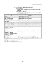
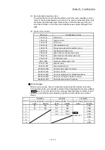
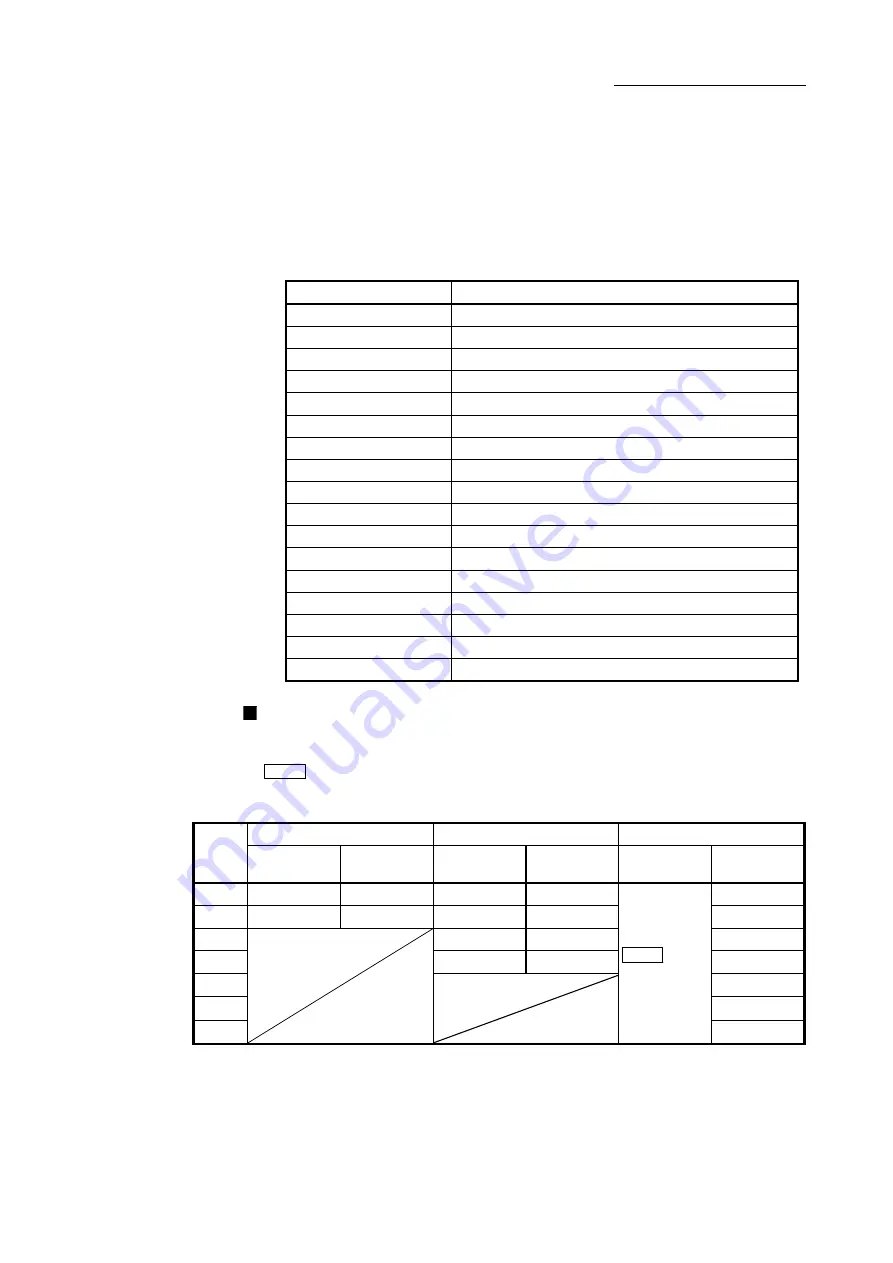
(4) Types of error codes
Error code
Classification of errors
001 to 009
Fatal errors
100 to 199
Common errors
200 to 299
OPR errors
300 to 399
JOG operation errors
400 to 499
Manual pulse generator operation errors
500 to 599
Positioning operation errors
600 to 699
Synchronous control input axis errors
700 to 799
Synchronous control output axis errors
800 to 899
I/F (Interface) errors
900 to 1099
Parameter setting range errors
1201 to 1209
Encoder errors
2000 to 2999
Servo amplifier errors
61440 to 61695
Errors for servo driver VCII series
61696 to 61951
Errors for inverter
61952 to 62207
Errors for stepping driver AlphaStep/5-phase
62208 to 62463
Errors for IAI electric actuator controller
62464 to 62719
Errors for servo driver VPH series
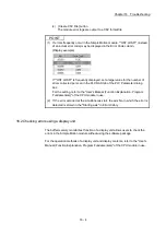
Error storage
When an error occurs, the error detection signal turns ON, and the error code
corresponding to the error details is stored in the following buffer memory address
(
Md.23
Axis error No.
) for axis error No. storage. Note that there is a delay of up to
operation cycle after the error detection signal turns ON until the error code is
stored.
Axis No.
LD77MS2 LD77MS4 LD77MS16
Error detection
signal
Buffer memory
address
Error detection
signal
Buffer memory
address
Error detection
signal
Buffer memory
address
1
X8 806 X8 806
Md.31
Status: b13
2406
2
X9 906 X9 906
2506
3 XA 1006
2606
4 XB
1106
2706
5
2806
to
to
16
3906
Summary of Contents for MELSEC-L Series
Page 2: ......
Page 30: ...MEMO ...
Page 70: ...2 10 Chapter 2 System Configuration MEMO ...
Page 83: ...3 13 Chapter 3 Specifications and Functions MEMO ...
Page 103: ...3 33 Chapter 3 Specifications and Functions MEMO ...
Page 107: ...3 37 Chapter 3 Specifications and Functions MEMO ...
Page 111: ...3 41 Chapter 3 Specifications and Functions MEMO ...
Page 115: ...3 45 Chapter 3 Specifications and Functions MEMO ...
Page 140: ...4 22 Chapter 4 Installation Wiring and Maintenance of the Product MEMO ...
Page 253: ...5 113 Chapter 5 Data Used for Positioning Control MEMO ...
Page 342: ...5 202 Chapter 5 Data Used for Positioning Control MEMO ...
Page 438: ...7 20 Chapter 7 Memory Configuration and Data Process MEMO ...
Page 440: ...MEMO ...
Page 485: ...9 25 Chapter 9 Major Positioning Control MEMO ...
Page 594: ...9 134 Chapter 9 Major Positioning Control MEMO ...
Page 624: ...10 30 Chapter 10 High Level Positioning Control MEMO ...
Page 656: ...11 32 Chapter 11 Manual Control MEMO ...
Page 690: ...12 34 Chapter 12 Expansion Control MEMO ...
Page 798: ...13 108 Chapter 13 Control Sub Functions MEMO ...
Page 866: ...14 68 Chapter 14 Common Functions MEMO ...
Page 884: ...15 18 Chapter 15 Dedicated Instructions MEMO ...
Page 899: ...16 15 Chapter 16 Troubleshooting MEMO ...
Page 1036: ...Appendix 88 Appendices MEMO ...
Page 1039: ......


