


16 - 35
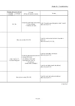
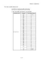
Chapter 16 Troubleshooting
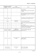
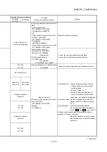
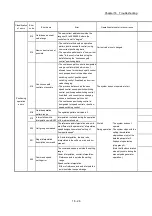
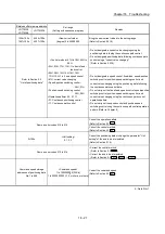
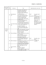
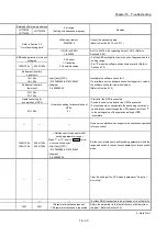
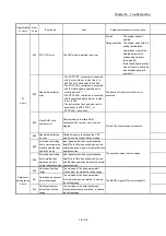
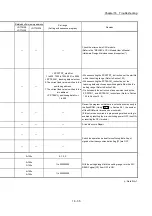
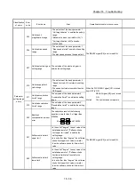
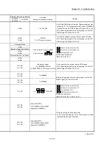
Related buffer memory address
Set range
(Setting with sequence program)
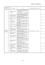
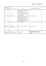
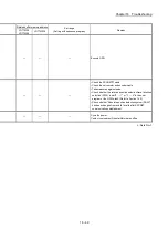
Remedy
LD77MS2
LD77MS4
LD77MS16
— —
—
Check the error code in CPU module.
(Refer to the "MELSEC-L CPU Module User's Manual
(Hardware Design, Maintenance and Inspection)".)
— —
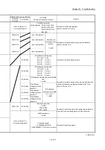
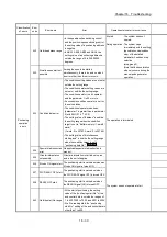
< ZP.PSTRT_ start No.>
1 to 600, 7000 to 7004, 9001 to 9004
< ZP.TEACH_ teaching data selection>
0: The current feed value is written to the
positioning address.
1: The current feed value is written to the
arc address.
< ZP.TEACH_ positioning data No.>
1 to 600
• When executing the ZP.PSTRT_ instruction, set the start No.
within the setting range. (Refer to Section 15.3)
• When executing the ZP.TEACH_ instruction, set the
teaching data selection and positioning data No. within the
setting range. (Refer to Section 15.4)
• Do not specify the instruction of a non-existent axis by the
ZP.PSTRT_ and ZP.TEACH_ instructions. (Refer to Section
15.3 to Section 15. 4)
— —
—
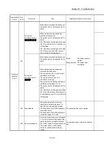
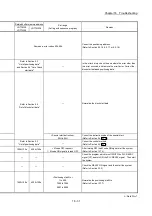
Review the program so that data is not written continuously to
the flash ROM. (Using "
Md.19
" in Section 5.6.1, the number
of flash ROM write times can be monitored.)
(If this error has occurred in a proper using method, writing is
enabled by resetting the error, switching power OFF, then ON,
or resetting the CPU module.)
—
—
—
A trouble occurs. Repair.
— —
—
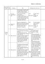
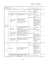
Switch the operation mode after confirming that all input
signals other than synchronization flag [X1] are OFF.
— —
—
0+150n
0, 1, 2, 3
With the setting brought into the setting range, turn the PLC
READY signal [Y0] from OFF to ON.
2+150n
3+150n
1 to 200000000
4+150n
5+150n
1 to 200000000
n: Axis No.-1
Summary of Contents for MELSEC-L Series
Page 2: ......
Page 30: ...MEMO ...
Page 70: ...2 10 Chapter 2 System Configuration MEMO ...
Page 83: ...3 13 Chapter 3 Specifications and Functions MEMO ...
Page 103: ...3 33 Chapter 3 Specifications and Functions MEMO ...
Page 107: ...3 37 Chapter 3 Specifications and Functions MEMO ...
Page 111: ...3 41 Chapter 3 Specifications and Functions MEMO ...
Page 115: ...3 45 Chapter 3 Specifications and Functions MEMO ...
Page 140: ...4 22 Chapter 4 Installation Wiring and Maintenance of the Product MEMO ...
Page 253: ...5 113 Chapter 5 Data Used for Positioning Control MEMO ...
Page 342: ...5 202 Chapter 5 Data Used for Positioning Control MEMO ...
Page 438: ...7 20 Chapter 7 Memory Configuration and Data Process MEMO ...
Page 440: ...MEMO ...
Page 485: ...9 25 Chapter 9 Major Positioning Control MEMO ...
Page 594: ...9 134 Chapter 9 Major Positioning Control MEMO ...
Page 624: ...10 30 Chapter 10 High Level Positioning Control MEMO ...
Page 656: ...11 32 Chapter 11 Manual Control MEMO ...
Page 690: ...12 34 Chapter 12 Expansion Control MEMO ...
Page 798: ...13 108 Chapter 13 Control Sub Functions MEMO ...
Page 866: ...14 68 Chapter 14 Common Functions MEMO ...
Page 884: ...15 18 Chapter 15 Dedicated Instructions MEMO ...
Page 899: ...16 15 Chapter 16 Troubleshooting MEMO ...
Page 1036: ...Appendix 88 Appendices MEMO ...
Page 1039: ......


