


14 - 39
Chapter 14 Common Functions
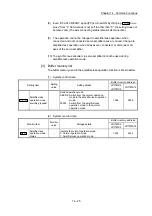
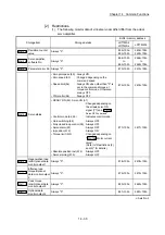
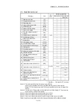
[MR-J4-_B_/MR-J4-_B_-RJ use]
Setting item
Setting details
Buffer memory address
LD77MS2
LD77MS4
LD77MS16
Input/output setti
ng
PA04
Forced stop deceleration function
selection
Disable deceleration stop
function at the master
axis and slave axis.
30104+200n 28404+100n
PD15 Driver communication setting
Set the master axis and
slave axis.
30210+200n
Set with
GX Works2
PD16
Driver communication setting
Master transmit data selection 1
Set the transmitted data
at master axis setting.
30211+200n
PD17
Driver communication setting
Master transmit data selection 2
30212+200n
PD20
Driver communication setting
Master axis No. selection 1 for slave
Set the axis No. of master
axis at slave axis setting.
30215+200n
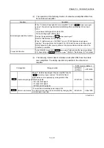
PD30
Master-slave operation - Torque
command coefficient on slave
Set the parameter at
slave axis setting.
30225+200n
PD31
Master-slave operation - Speed limit
coefficient on slave
30226+200n
PD32
Master-slave operation - Speed limit
adjusted value on slave
30227+200n
n: Axis No.-1
(Note-1): When the slave axis is not allocated for the master axis, the operation is normal operation only of
master axis.
(Note-2): For LD77MS16, the above servo parameters of PD_ are not allocated to the buffer memory.
Write them to Simple Motion module with GX Works2.
(Note-3): At slave setting, set only "Driver communication setting Master axis No. selection 1 for slave (PD20)" in
the master axis No. selection normally.
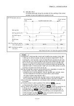
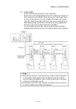
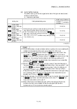
POINT
(1) The servo parameters are transmitted from Simple Motion module to servo
amplifier after power supply ON or reset of PLC CPU. Execute flash ROM
writing of Simple Motion module after writing the servo parameter to buffer
memory, and then turn the power supply ON or reset the PLC CPU.
(2) The servo parameters for driver communication setting (PA04, PD15 to PD17,
PD20) become valid by turning the servo amplifier's power supply OFF to ON.
Turn the servo amplifier's power supply OFF to ON after executing the above
(1). Then, turn the system's power supply ON or reset the PLC CPU.
(3) In the driver communication function, the torque generation direction for slave
axis can be set in "Rotation direction selection/travel direction selection
(PA14)".
Summary of Contents for MELSEC-L Series
Page 2: ......
Page 30: ...MEMO ...
Page 70: ...2 10 Chapter 2 System Configuration MEMO ...
Page 83: ...3 13 Chapter 3 Specifications and Functions MEMO ...
Page 103: ...3 33 Chapter 3 Specifications and Functions MEMO ...
Page 107: ...3 37 Chapter 3 Specifications and Functions MEMO ...
Page 111: ...3 41 Chapter 3 Specifications and Functions MEMO ...
Page 115: ...3 45 Chapter 3 Specifications and Functions MEMO ...
Page 140: ...4 22 Chapter 4 Installation Wiring and Maintenance of the Product MEMO ...
Page 253: ...5 113 Chapter 5 Data Used for Positioning Control MEMO ...
Page 342: ...5 202 Chapter 5 Data Used for Positioning Control MEMO ...
Page 438: ...7 20 Chapter 7 Memory Configuration and Data Process MEMO ...
Page 440: ...MEMO ...
Page 485: ...9 25 Chapter 9 Major Positioning Control MEMO ...
Page 594: ...9 134 Chapter 9 Major Positioning Control MEMO ...
Page 624: ...10 30 Chapter 10 High Level Positioning Control MEMO ...
Page 656: ...11 32 Chapter 11 Manual Control MEMO ...
Page 690: ...12 34 Chapter 12 Expansion Control MEMO ...
Page 798: ...13 108 Chapter 13 Control Sub Functions MEMO ...
Page 866: ...14 68 Chapter 14 Common Functions MEMO ...
Page 884: ...15 18 Chapter 15 Dedicated Instructions MEMO ...
Page 899: ...16 15 Chapter 16 Troubleshooting MEMO ...
Page 1036: ...Appendix 88 Appendices MEMO ...
Page 1039: ......


